
80W power amplifier MJ3001 and MJ2501

This circuit describes a low-cost Hi-Fi quality power amplifier that can be configured in five different ways, allowing for output power ranging from 20 W to 80 W RMS. The design emphasizes the importance of selecting appropriate transistors for optimal performance. Specifically, the end transistors, labeled T3 and T4, should be measured for their current gain, denoted as hfe or β. A variation in the hfe greater than 30% between these transistors may lead to audio distortion or a lack of clarity in sound reproduction. For this design, the MJ3001 and MJ2501 transistors are recommended, as they typically present a variation of around 5%, which is acceptable for maintaining sound quality.
Before the initial power-up of the amplifier, it is crucial to short-circuit the inputs to prevent any unintended signals from affecting the measurements. A milliampere meter (mA-meter) should be connected to the output to monitor the DC current during this setup phase. Upon powering the amplifier, the R13 potentiometer should be adjusted to minimize the DC output current to a few microamperes. This adjustment is vital to ensure that the amplifier operates correctly without damaging the connected speakers or causing distortion in the audio output. This procedure is essential for achieving a reliable and high-fidelity amplification performance.This is a very simple, low cost, Hi-Fi quality power amplifier. You can build it 5 ways, like its shown in the table (from 20 W to 80 W RMS). The first thing that you must do, is to measure the end transistors (T3 and T4) amplifying coefficient, the hfe or β. If their disagreement is bigger than 30 %, the amplifier would not give a clear sound. I used MJ3001 and MJ2501 transistors, and this disagreement was around 5%. Before the first turning on you must short circuit the inputs of the amp, and put a mA-meter on the output, than turn the amplifier on, and tune the R13 pot, to decrease the DC current on the output, to some uA-s, or in a lucky situation to 🔗 External reference
Related Circuits
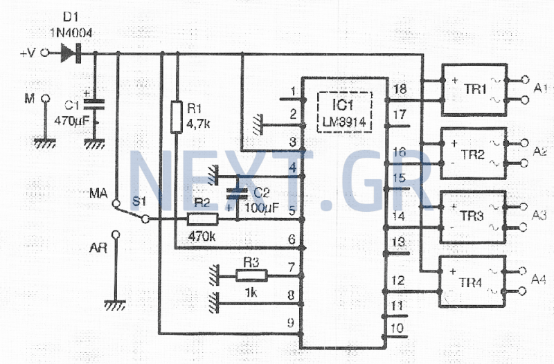
It is common to require the sequential powering of devices, which can involve managing numerous switches that are often in hard-to-reach locations, particularly for informational devices and their connections. This sequential actuator autonomously activates one to four devices in...
High-quality amplifier for headphones electronics project. No need for preamplifier. Circuit diagram. The described project involves the design of a high-quality headphone amplifier that operates without the necessity of a preamplifier stage. This simplifies the circuit while still delivering superior...
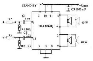
This car audio amplifier provides an output of 40 watts when connected to a 2-ohm speaker. The amplifier circuit delivers a power output of 40 watts per channel at a 2-ohm load and 22 watts at a 4-ohm load....
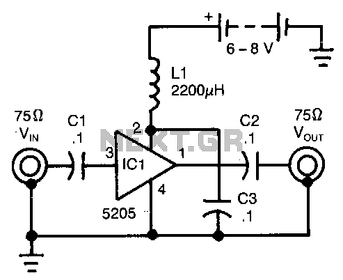
This wideband amplifier utilizes only five components. External signals are introduced to pin 3 of IC1 through an AC coupling capacitor, C1. After amplification, the enhanced signals from pin 1 of IC1 are transmitted to the output via capacitor...
A center tap transformer is required. For instance, to obtain a 12V output, connect J1 to the 15V transformer output, J2 to 0V, and J3 to another 15V. A center tap transformer is a specialized transformer that has a secondary...
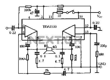
TDA1510 is an audio power amplifier from Philips. This integrated circuit (IC) includes features such as load short protection, open load detection, and an overheat protection circuit. It offers stable output voltage, excellent ripple rejection performance, requires fewer external...