
Headphone Amplifier

The described project involves the design of a high-quality headphone amplifier that operates without the necessity of a preamplifier stage. This simplifies the circuit while still delivering superior audio performance. The amplifier is intended to drive headphones directly, making it suitable for various applications, including personal audio devices and DIY audio projects.
The circuit typically consists of an operational amplifier (op-amp) as the core amplification element. The op-amp is configured in a non-inverting mode to ensure that the output signal is in phase with the input signal, providing a clean amplification of the audio signal. The gain of the amplifier can be set using resistors in the feedback loop, allowing for customization based on the headphones' impedance and sensitivity.
Power supply considerations are crucial for achieving high-quality audio output. A dual power supply, often ±15V or ±12V, is recommended to provide sufficient headroom for the audio signal, minimizing distortion and allowing for dynamic range. Capacitors are used for decoupling the power supply to filter out noise and ensure stable operation of the op-amp.
Input and output coupling capacitors are typically included to block any DC offset from the audio source and headphones, respectively. This ensures that only the AC audio signal is passed through, protecting the headphones from potential damage caused by DC voltage.
The circuit diagram will illustrate the connections between the op-amp, resistors, capacitors, and power supply. Additionally, it may include details on the layout for PCB design, ensuring that signal integrity is maintained and minimizing interference from external sources.
Overall, this headphone amplifier project is designed to provide high fidelity audio reproduction with minimal complexity, making it an excellent choice for audio enthusiasts and engineers looking to develop a reliable and effective amplification solution for headphones.high quality amplifier for headphones electronics project. no need for preamplifier. circuit diagram. 🔗 External reference
Related Circuits
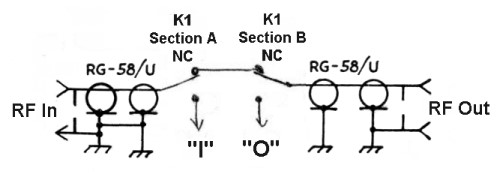
In a grid-driven amplifier, it is essential to match the low impedance of the driving transmitter (typically 50 ohms) to the high impedance input of the tube (usually several thousand to several million ohms). The signal from the input...

A lens is a custom view of the content in the repository. It can be considered a sophisticated type of list that allows users to view content through the perspectives of trusted organizations and individuals. Class D amplifiers exhibit...
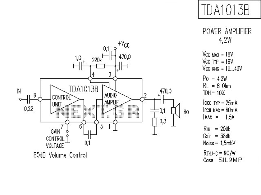
The following is a circuit for a 4-watt audio amplifier. The amplifier utilizes an integrated audio amplifier chip, TDA1013B, which is capable of delivering an audio power output of up to 4W at an 8-ohm load. Its wide supply...
The RF amplifier is similar to the one used in the 2.5 MHz amplifier. At a frequency of 10 MHz, the capacitances of a power MOSFET become significant. Noiseless feedback using transformers is no longer straightforward. Intermodulation and overtones...
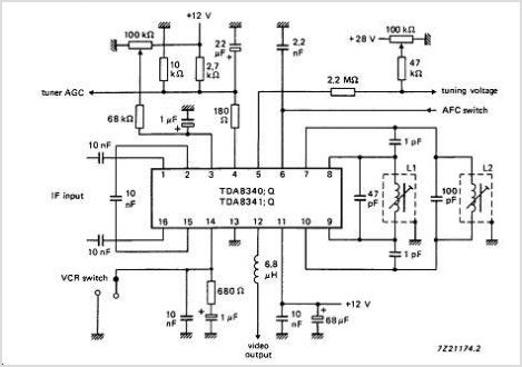
The TDA9813T is an integrated circuit designed for processing vision intermediate frequency (IF) signals and dual frequency modulation (FM) demodulation of sound. It operates with a single reference QSS-IF in television (TV) and video cassette recorder (VCR) applications, specifically...
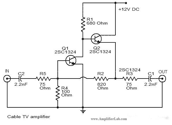
The circuit diagram of a cable TV amplifier has been provided. This cable TV amplifier circuit includes two transistors, Q1 and Q2. The cable TV amplifier circuit is designed to enhance the signal strength of cable television signals, improving the...