
Dual Regulated Power Supply

A center tap transformer is a specialized transformer that has a secondary winding with a center tap, allowing for multiple output voltages. In this configuration, the center tap serves as a reference point, typically at 0V, which enables the generation of dual voltages from a single transformer.
For a typical application where a 12V output is required, the transformer should have a secondary winding rated for 30V (15V-0V-15V). In this case, J1 is connected to one end of the secondary winding (15V), J2 is connected to the center tap (0V), and J3 is connected to the other end of the secondary winding (another 15V).
This setup allows for the extraction of 12V across J1 and J2, or J2 and J3, depending on the load connection. The center tap provides a stable reference point, which is essential for various applications, including power supply circuits for amplifiers or other electronic devices.
When designing circuits with a center tap transformer, it is crucial to ensure that the transformer is rated for the required current and voltage specifications. Additionally, appropriate filtering and regulation may be needed on the output to achieve a stable and clean DC voltage, particularly if the load requires precise voltage levels or low ripple.You need center tap transformer. for example, if you need 12v output, you should connect J1 to 15v transformer output, J2 connected to 0v and J3 connected to another 15V. 🔗 External reference
Related Circuits
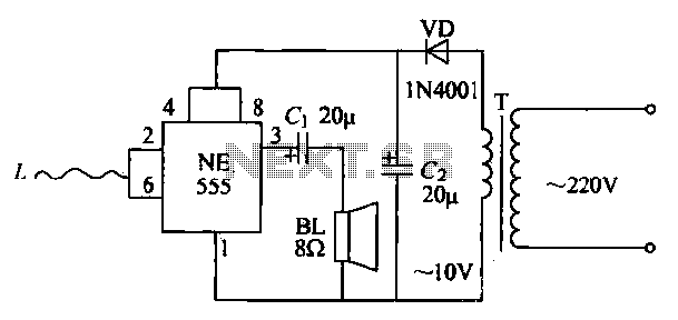
The manpower inductive alarm circuit is simple and practical. When a person's hand approaches the sensing line, the alarm emits a sound, making it suitable for male electrical burglar alarms. The induction line L is approximately 50 cm long....
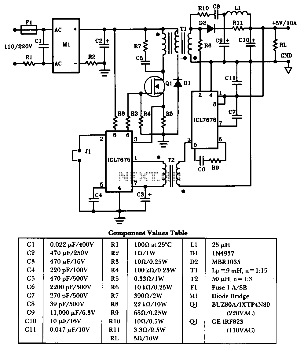
The schematic illustrates a 50W power supply providing a 5V, 10A output. It operates as a flyback converter in continuous mode. The circuit incorporates both primary and secondary side controllers, offering full protection against fault conditions such as overcurrent....

Low power 5V switching regulator power supply. Visit the corresponding page for an explanation of the related circuit diagram. The low power 5V switching regulator is designed to efficiently convert a higher input voltage to a stable 5V output while...
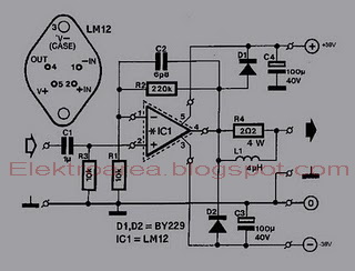
This is an 80W power amplifier OCL circuit that utilizes the integrated circuit LM12. It effectively enhances bass and treble performance. When connected to a CD player, it produces high-quality sound, especially when paired with a good pre-tone control....
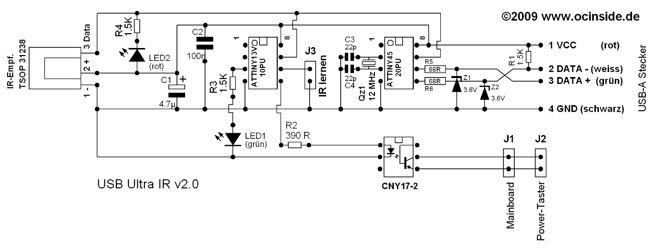
This Atmel integrated circuit operates at a clock frequency of 12 MHz, facilitating communication between an infrared receiver and a personal computer. This setup enables the processing of signals by infrared receiver software, such as Girder. When a valid...
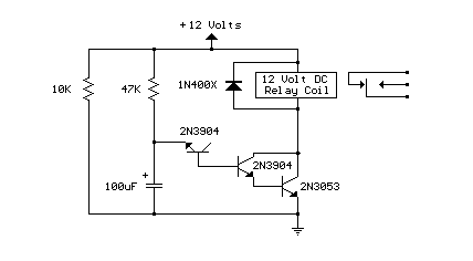
Here's a power-on time delay relay circuit that takes advantage of the emitter/base breakdown voltage of an ordinary bi-polar transistor. The reverse connected emitter/base junction of a 2N3904 transistor is used as an 8 volt zener diode which creates...