
SM7232, CS7232 dimming control ASIC circuit

The SM7232 dimmer circuit is designed to provide a flexible and user-friendly lighting control solution. The circuit operates on a standard AC supply, with the integrated SM7232 managing the dimming functionality through a combination of touch-sensitive inputs and phase-locked loop (PLL) technology. The VDD pin serves as the primary power supply, while VSS connects to the ground, establishing a stable operating environment for the IC.
The functionality of the dimmer is heavily reliant on the touch-sensitive interface. The capacitive touch sheet connected to pin 5 (SEN) allows users to control the lighting with a simple touch. The resistors R4 and R5 are critical in defining the sensitivity of this touch interface, where R4 acts as a high-impedance input resistor, and R5 ensures user safety by limiting current flow. The circuit is designed to respond to touch durations, enabling users to either toggle the lights on or off with a quick tap or adjust the brightness with a longer press.
The SYN pin plays a vital role in synchronizing the dimming operation with the input AC frequency. The PLL circuit stabilizes the output frequency, ensuring consistent performance even under varying load conditions. The output pulse generated at pin 8 (OUT) can be used to drive additional circuitry or directly control a light source.
The inclusion of a half-wave rectifier circuit composed of diodes (VD1 and VD3), along with resistors and capacitors, ensures that the SM7232 receives a stable 5V DC supply. This regulated voltage is essential for the reliable operation of the IC, allowing it to perform its dimming functions effectively. The filtering capacitors (C2 and C1) mitigate electrical noise, enhancing the circuit's overall robustness.
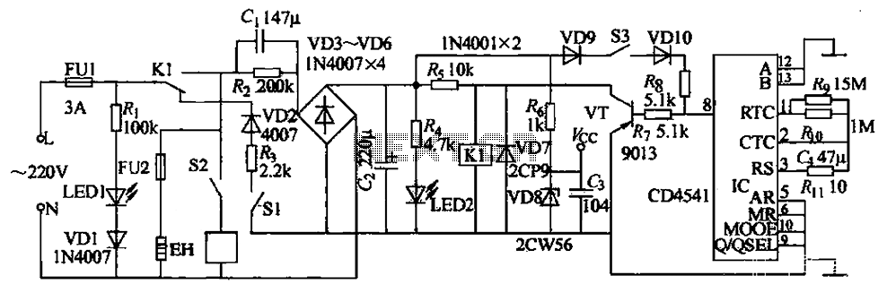
In summary, the SM7232 dimmer circuit is a sophisticated lighting control solution that combines touch sensitivity, phase synchronization, and voltage regulation to provide a seamless user experience in dimming and controlling lighting fixtures.Circuit core device is a dimmer SM7232 specific integrated circuits, which leads to the foot of the eight functions are as follows: 1 pin VDD, the positive power supply terminal; 2 feet DOZE, 5 feet SEN, 6 feet SLAVE is a phase shift control input, wherein 5 feet touch control input signal by hand touch R5, R4 two high-value input resistor, when the touch time within 39ms ~ 399ms, to be completed by open, turn off the lights, a touch longer than 399ms (about 0.4s). Turn on the lights or dimming can be done for a long time to catch a touch sheet M, the lights of the automatic fade from dark to light and from light fades, you let go deemed appropriate, namely fixed brightness, as long as you want to turn off the lights briefly touch (small in 0.4s) can be, and then touch briefly (less than 0.4s) but also turn on the lights, and keep the original tone set brightness function {6 feet and 5 feet similar, but with a special internal logic, mainly for long distance control when the circuit less susceptible to interference formed malfunction as; 4 feet SYN, the input power frequency synchronization by the internal PLL locking phase shifting circuit as a memory circuit and brightness, producing a zero phase reference raw output trigger pulse; 3 feet for the CAP, internal PLL low pass filter capacitor external terminals; 7 feet vss, negative power supply terminal; 8 feet OUT, is the trigger pulse output.
VD1, VD3, Rl and C3 form resistance voltage half-wave rectifier voltage regulator circuit, the output DC 5v for SM7232 electricity. R2 provides a synchronization signal to 4 feet. C2 filter out spikes interference. cl is PLL filter capacitor. R6 is vs SCR trigger signal. R3 resistance will affect the size of the touch sensitivity, and can be selected at 220k O ~ 680k O Room.
Two high-impedance resistor R4 is connected to a touch sheet M, R5 is to ensure the absolute safety of the user.
Related Circuits
The circuit element appears to be problematic, particularly with the Shu component. After a prolonged period following the activation of the start button, there are indications of unexpected behavior, such as the turtles producing sperm-like substances. The Pi Wen...
The AC Motor Speed Controller is designed to regulate the speed of AC motors with carbon brushes, applicable to devices such as drills, saws, and vacuum cleaners. The AC Motor Speed Controller operates by adjusting the voltage and current supplied...

A high-power and efficient 100W power amplifier electronic project can be designed using the STK404 audio power amplifier hybrid ICs. These ICs consist of optimally designed discrete component power amplifier circuits that have been miniaturized using SANYO's unique insulated...
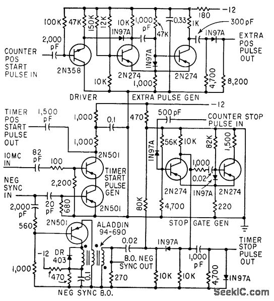
The timer start-pulse generator is a fast series-transistor coincidence circuit. The slope-gate generator is a one-shot multivibrator that prevents the 1N97A diode from passing the blocking oscillator's negative sync pulse until the multivibrator fires. This circuit is utilized to...
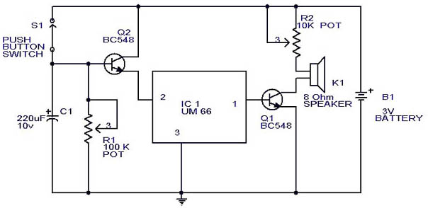
This circuit is a slight modification of a previous design. In the earlier version, the switch needed to be held down for the entire duration of the music playback. In this updated circuit, pressing the push button once charges...
In night photography, long exposures are common, sometimes lasting several seconds to several minutes. HDR techniques often require taking a series of nine or more photos. Holding a remote trigger for an extended period can be tedious, leading to...