
Basic reference transistor bias circuit - Mixed Negative feedback

The basic reference transistor bias circuit utilizing mixed negative feedback is a fundamental electronic configuration designed to stabilize the operating point of a transistor. This circuit typically employs a combination of resistive feedback and emitter degeneration to enhance linearity and thermal stability.
In this configuration, a transistor is connected in a common-emitter arrangement, where the input signal is applied to the base terminal. The collector is connected to a power supply, while the emitter is connected through a resistor to ground. The mixed negative feedback is achieved by incorporating resistors that connect the collector to the base, providing a fraction of the output voltage back to the input. This feedback mechanism helps to reduce the gain sensitivity to variations in transistor parameters and temperature changes.
The biasing network is crucial for ensuring that the transistor operates in the active region, preventing it from entering saturation or cutoff during signal variations. The design of the resistor values is critical, as they determine the biasing current and, consequently, the quiescent point (Q-point) of the transistor. Proper selection of these components allows for a stable operation over a range of conditions, making this circuit widely used in amplifier designs and other applications requiring reliable transistor performance.
In summary, the basic reference transistor bias circuit with mixed negative feedback is essential for achieving stable and linear transistor operation, which is vital for a variety of electronic applications. Basic reference transistor bias circuit - Mixed Negative feedback
Related Circuits
The two circuits below illustrate opening a relay contact a short time after the ignition or light switch is turned off. The capacitor is charged and the relay is closed when the voltage at the diode anode rises to...
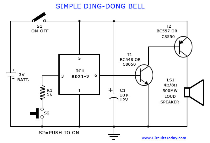
A tone generator circuit, which can be used to create a simple calling bell circuit, is illustrated here. It is constructed using the 8021 integrated circuit (IC), which includes built-in circuitry for producing a "ding-dong" sound. The tone generator circuit...

This portable AM/FM radio circuit is designed using the LA1800 integrated circuit (IC) along with several external components. The LA1800, manufactured by Sanyo Semiconductors, requires only a few additional components for its operation. The output signal is directed to...
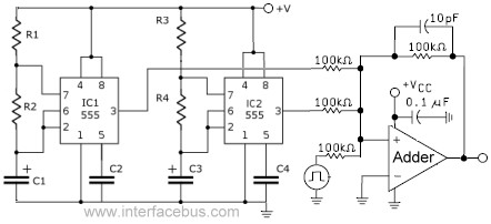
This circuit combines the outputs from two distinct 555 multivibrators using a summing operational amplifier (Op Amp). It serves to illustrate an alternative implementation of a 555 timer, with most background calculations addressed in other sections. The standard configuration...
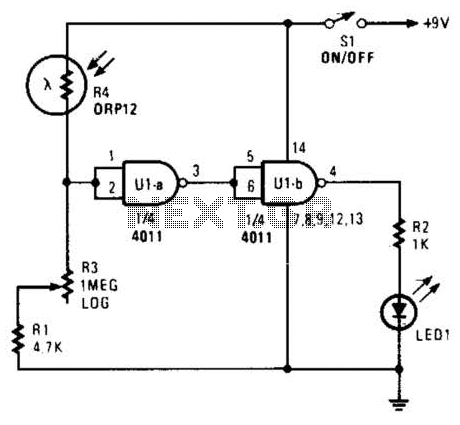
Two gates of a 4011 IC are utilized as a comparator. When the resistance of R4 decreases, the voltage at pins 1 and 2 increases, resulting in a logic zero at pin 3. This causes pin 4 to go...
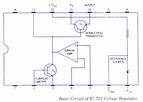
The working and block diagram of the IC 723 Voltage Regulator is provided along with the circuit diagram and applications. The IC 723 is a voltage regulator integrated circuit that is widely used for providing a stable output voltage. It...