
8W Flouroscent lamp driver

The fluorescent lamp driver circuit is designed to operate efficiently by utilizing two transistors configured as an oscillator. The transistors, specifically the 2SC 1983 model, are chosen for their suitability in switching applications and high-frequency operation. The oscillator generates a frequency of around 1 kHz, which is ideal for driving fluorescent lamps, as it allows for effective excitation of the gas within the tube.
Capacitive ballasting is employed in this design to limit the current flowing through the fluorescent tube, preventing excessive heating and prolonging the lamp's lifespan. The circuit architecture ensures that the transistors do not enter saturation, which is critical for maintaining a stable output and reducing power losses. This design consideration results in a cleaner sine wave output, characterized by low harmonic distortion and minimal electromagnetic interference.
The transformer design is integral to the circuit's operation. The primary winding, constructed with 0.8 mm diameter enameled copper wire, should be wound first around the ferrite core. The secondary winding, made with 0.4 mm diameter enameled copper wire, is then wound on top of the primary. The number of turns for each winding is specified in the schematic, which is crucial for achieving the desired voltage transformation and ensuring that the fluorescent tube operates efficiently.
Overall, this circuit represents a practical and effective solution for driving fluorescent lamps, balancing efficiency, performance, and simplicity in its design.Here is the schematic of a simple flouroscent lamp driver circuit based on two transistors. The circuit uses capacitive ballasting for driving the tube. An 8 W standard flouroscent tube can be efficiently driven using the circuit. The two transistors (2Sc 1983) with associated components forms a oscillator around 1KHz. The oscillator is wired so that saturation condition of the transistors are prohibited. This adds on to the efficiency of the circuit. The circuit produces a clean sine wave with very less noise. The winding details(no of turns) are given in the circuit. Use 0. 8 mm dia enameled copper wire for primary and 0. 4 mm dia enameled copper wire for secondary. The core can be a ferrite core. The primary should be wound first and secondary on top of it. 🔗 External reference
Related Circuits
Many sites do not provide circuits for driving these transformers; they simply state that they are ineffective. However, this assertion is contested. A circuit has been developed that operates effectively, with significant effort invested in determining the resonant frequency...
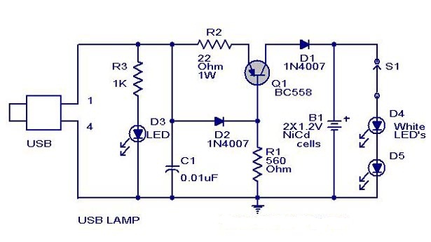
A simple USB-powered lamp designed to illuminate a desktop during power outages. The circuit operates at 5 volts sourced from a USB port. The 5V from the USB is directed through a current-limiting resistor (R2) and a transistor (Q1)....
The full wave phase control circuit presented below was sourced from an RCA power circuits book published in 1969. The load is connected in series with the AC line, and four diodes provide a full wave rectified voltage to...
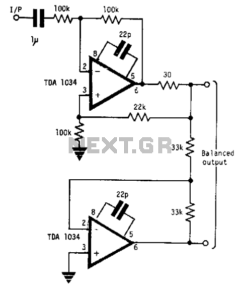
This circuit will handle +24 dBm with ± 12 volts supply using TDA 1034s. This circuit uses current and voltage feedback. The described circuit utilizes the TDA 1034S integrated circuit, which is designed for audio applications and can handle an...
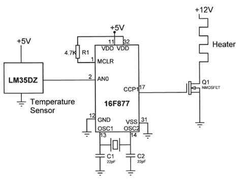
The electrical circuit diagram of this temperature control circuit consists of a 3-pin analog temperature sensor (LM35DZ), a built-in A/D converter microcontroller (PIC16F877), and the heater driver (IRL1004). The temperature control circuit utilizes the LM35DZ, a precision analog temperature sensor...
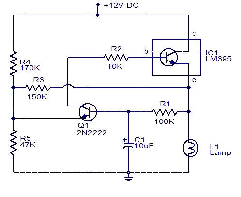
This circuit for a powerful flashing lamp is suitable for use in vehicles. The LM395 integrated circuit, also known as a super-transistor, is a highly robust monolithic power transistor that includes features such as thermal protection and current limiting....