
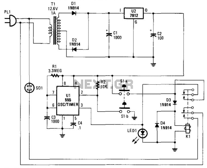
9 Second Digital Readout Countdown Timer

The described circuit functions as a visual timer employing a combination of a CD4010 up/down counter, a 555 timer, and a CD4511 BCD to 7-segment decoder. The operation begins when the switch is closed, which sets the counter to its maximum preset value of 9. At this point, the 555 timer is disabled, preventing any clock signal from decrementing the counter. Upon opening the switch, the timer initiates a clock pulse approximately every second, causing the counter to decrement sequentially from 9 down to 0.
The transition to a zero count triggers the carry-out signal at pin 7, which activates a 12-volt relay. This relay serves a dual purpose: it halts the clock signal by sending a low signal to the reset line (pin 4) and remains energized until the switch is closed again. This design allows for a reset of the counter back to its initial state of 9, effectively restarting the timing cycle.
The clock pulse duration can be fine-tuned by adjusting the resistor connected to pin 3 of the 555 timer, providing flexibility in the timing application. The CD4510 counter is versatile, allowing for presetting to any value between 0 and 9 via its preset inputs (pins 4, 12, 13, and 3) and can be reset to zero through the reset line (pin 9). The counting direction is dictated by the UP/DOWN input (pin 10), with a high signal indicating an upward count and a low signal indicating a downward count.
The CD4511 decoder enhances the circuit by converting the BCD output from the counter into a format suitable for driving a 7-segment display. It can source sufficient current to illuminate the display directly, with the latch-enable, lamp-test, and blanking features allowing for additional control over the visual output. The requirement for a common cathode LED display ensures compatibility with the positive voltage needed for segment illumination.
This circuit is suitable for applications requiring a simple visual timer, such as in educational projects, hobby electronics, or basic timing functions in larger systems. Its modular design allows for easy adjustments and modifications, making it an excellent choice for experimentation and learning in electronics.This circuit provides a visual 9 second delay using a 7 segment digital readout LED. When the switch is closed, the CD4010 up/down counter is preset to 9 and the 555 timer is disabled with the output held high. When the switch is opened, the timer produces an approximate 1 second clock signal, decrementing the counter until the 0 count is reached.
When the zero count is reached, the `carry out` signal at pin 7 of the counter moves low, energizing the 12 volt relay and stopping the clock with a low signal on the reset line (pin 4). The relay will remain energized until the switch is again closed, resetting the counter to 9. The 1 second clock signal from the 555 timer can be adjusted slightly longer or shorter by increasing or decreasing the resistor value at pin 3 of the timer.
The CD4510 is a CMOS Presettable BCD Up/Down counter which can be preset to any number between 0 and 9 with a high level on the PRESET ENABLE line, (pin 1) or reset to 0 with a high level on the RESET line (pin 9). Inputs for presetting the counter (P1, P2, P3, P4) are on pins (4, 12, 13, 3) respectively. The counter advances up or down on each positive-going clock transition (pin 15) and the counting direction (up or down) is controlled by the logic level on the UP/DOWN input (pin 10, high=up, low=down).
The CARRY-IN signal (pin 5) disables the counter with a high logic level. The CD4511 is a CMOS BCD to 7 segment latch decoder capable of sourcing up to 25 mA which allows it to drive LEDs and other displays directly. A LATCH-ENABLE line (pin 5, active low) stores data from the BCD input lines. A LAMP-TEST input (pin 3, active low) can be used to illuminate all 7 segments, and a BLANKING input (pin 4, active low) can be used to turn all segments off.
The LED display must be a common cathode type so that the segments are illuminated with a positive voltage on their respective connections. 🔗 External reference
Related Circuits
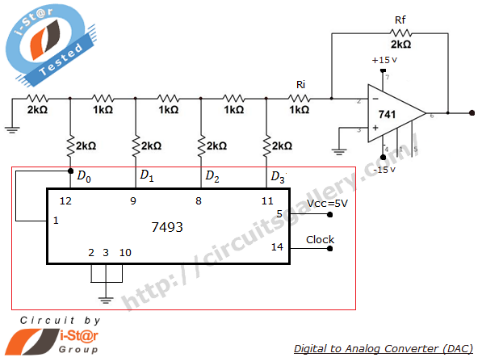
A Digital to Analog Converter (DAC) is utilized to produce an analog voltage that corresponds to input digital data. Binary data can be transformed into its analog equivalent using an R-2R ladder network combined with a summing amplifier, which...
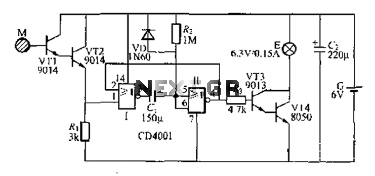
A two-battery powered light touch delay circuit designed for convenience at night. It can be placed on a bed pillow, and when the metal contact M under the capsule is touched, a small lamp will automatically light up. The...
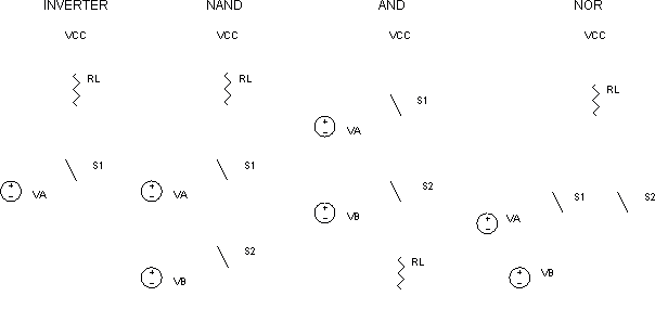
You're simulating a circuit, it requires several digital gates, but you don't have a mixed-mode simulator. What to do? One solution involves creating simplified versions of the logic functions. To do this, we look to the NMOS transistor implementation...
This circuit relies on the input of a correct sequence code. An incorrect number that is not part of the code triggers a reset of the circuit. When the correct code is entered, Q2 activates relay K1 for a...
AN79 Linear Technology AN79 modifies methods presented in AN74, allowing for the verification of 30 nanosecond amplifier settling times with 0.1% resolution. The sampling-based technique used is detailed, and results are presented. Appendices cover oscilloscope overdrive issues, the construction...
Suitable for cutting off an appliance or other AC load, this timer will cut the AC power after a period determined by R1/C3, as shown, for about 40 minutes. K1 is a relay that should handle about 10 A....