
Appliance Cutoff Timer

The described circuit utilizes a timer mechanism to control the power supply to an AC load, effectively enabling or disabling the load after a predetermined duration. The timer is configured using a resistor (R1) and a capacitor (C3), which together set the timing interval to approximately 40 minutes. This timing function is critical for applications where automatic shut-off is required to prevent overheating, energy wastage, or safety hazards.
The relay (K1) serves as the switching device, capable of handling a load current of up to 10 A, making it suitable for a variety of household appliances. The relay is activated by the timer circuit, which closes the relay contacts to allow current flow to the load when the timer initiates the cycle. When the timing period expires, the relay is deactivated, cutting off the AC power supply to the load.
Activation of the timer is achieved through the use of momentary switches (S1A and S1B). These switches are designed to be pressed briefly to start the timing cycle, providing user control over when the timer begins its countdown. The momentary nature of these switches ensures that the timer starts only when intended, preventing accidental activation.
Overall, this circuit design is efficient and practical for applications requiring timed control of AC loads, ensuring that devices can operate for a set duration before being automatically turned off. The combination of resistive and capacitive components in the timing circuit allows for precise control over the timing interval, while the relay and momentary switches provide robust operational capabilities. Suitable for cutting off an appliance or other ac load, this timer will cut the ac power after a period determined b y R1/C3, as shown, for about 40 minutes. Kl is a relay that should handle about 10 A. SlA and SIB is a momentary switch that starts the timer cycle.
Related Circuits
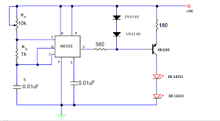
A TV remote jammer circuit using the NE555 timer IC. This device allows users to watch their favorite TV channels without interruptions, as it prevents others from changing the channel using a remote control when the circuit is activated....
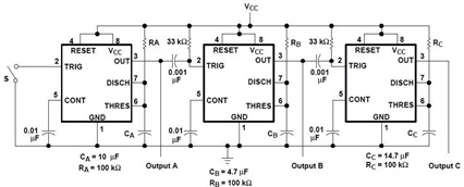
A sequential timer circuit device is utilized in various applications for initializing conditions during start-up or for activating test signals in sequences, such as in test equipment devices. The circuit diagram below illustrates a sequencer circuit with potential applications...
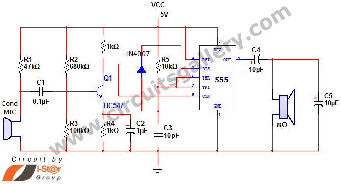
This document discusses a simple project utilizing the 555 timer IC. The 555 timer IC can be configured as an audio amplifier using an astable multivibrator configuration. It performs pulse width modulation (PWM) on an audio signal. The current...
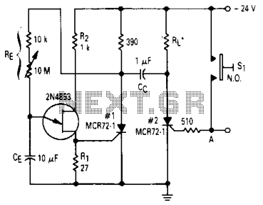
After one cycle of operation, SCR1 will be activated, resulting in a low voltage being applied to the UJT emitter circuit, which interrupts the tuning function. When pushbutton SI is pressed, or a positive pulse is applied at point...

The Servo Timer II was primarily designed for parachute deployment on water rockets but can be used for other applications. The timer controls a single RC servo motor that can open a latch on a parachute door. Once triggered,...
Control electrical appliances using a PC. This circuit utilizes the printer port of a PC for control applications through software and some interface hardware. The interface circuit is included. The described circuit leverages the parallel printer port (also known as...