
DIGITAL LOCK CIRCUIT

The circuit functions as a basic code entry system, utilizing a combination of digital logic and analog components to ensure that only a specific sequence of inputs can trigger the relay operation. The primary components include a microcontroller or a simple logic gate arrangement to evaluate the entered code, a transistor (Q2) to switch the relay, and a timing capacitor (C3) that defines the duration of the relay activation.
Upon entering a sequence, the system checks each digit against a predefined code stored in memory. If an incorrect digit is detected, the circuit resets, ensuring that no unauthorized access is granted. This reset mechanism can be implemented using a flip-flop or a simple reset line that is activated by the incorrect input.
When the correct sequence is entered, Q2 is triggered, allowing current to flow through relay K1. The relay then closes its contacts, which can be used to control various external devices, such as alarms, locks, or indicators. The duration of this activation is governed by the charge time of capacitor C3, which can be calculated based on the RC time constant, where the resistance in the circuit and the capacitance determine how long the relay remains activated before returning to its default state.
The design of this circuit can be further enhanced by incorporating features such as debounce logic for the input keys to prevent false triggering, as well as visual indicators (LEDs) to provide feedback on the status of the code entry process. Additionally, the circuit could be expanded with security features, such as a lockout period after multiple incorrect attempts, to increase its robustness against unauthorized access attempts.This circuit depends on the entry of a correct sequence code. An incorrect number that is not part of the code causes the circuit to reset. When the correct code is entered, Q2 operates relay K1 for a short time, depending on C3. 🔗 External reference
Related Circuits
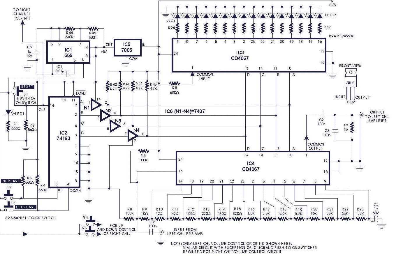
Circuit of a digital volume control using six discrete ICs, including a 5V regulator, is presented. IC1 (555) is configured to function as astable flip-flop. Its frequency or period may be adjusted by proper choice of resistors R44, R45...
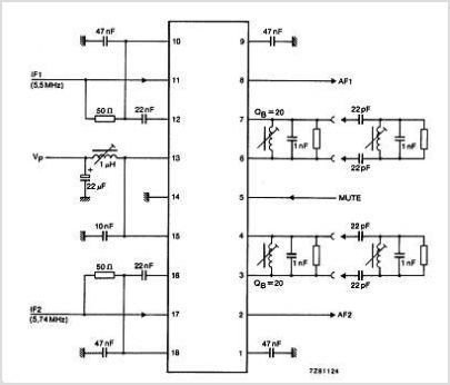
The TDA3567 is a monolithic integrated decoder designed for the NTSC color television standards. It incorporates all the necessary functions for the demodulation of NTSC signals. Additionally, it features a luminance amplifier and an RGB matrix amplifier. These amplifiers...
There are many circuits for low voltage regulators. For higher voltages, such as supplies for valve circuits, the situation is different. Low voltage regulators are widely utilized in electronic circuits to provide a stable output voltage from a varying input...
This is another kit in our self-sufficiency range. We also have a 12v fluoro inverter kit for those who need to operate 20watt to 40watt fluorescent lamps from a 12v supply. We will be introducing a number of kits...
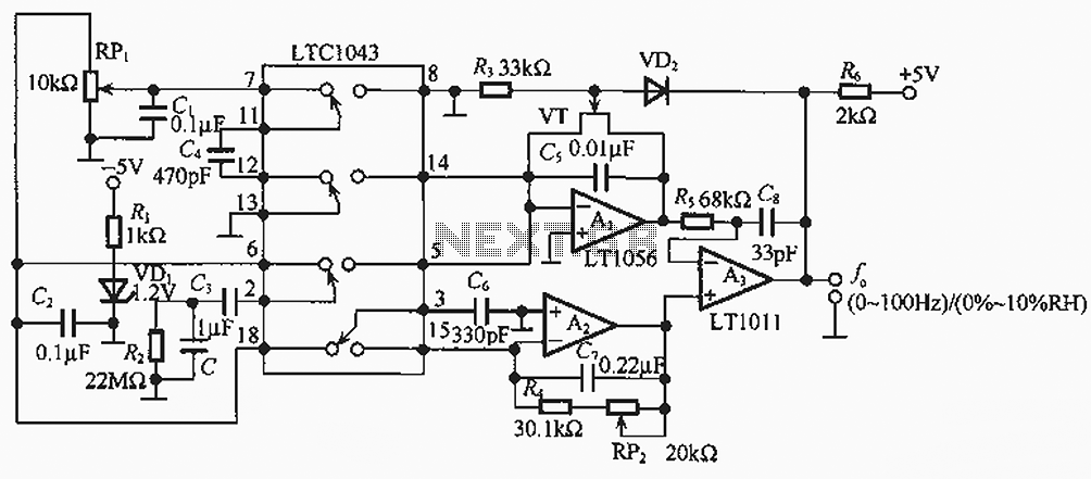
The humidity/frequency conversion circuit operates similarly to the previously mentioned humidity sensors. At a humidity level of 76%, the equivalent capacitance is 500 pF, with a capacitive relative humidity variation rate of +1.7 pF/%. The circuit includes an integrating...

Most thefts occur after midnight when individuals enter the second phase of sleep known as 'paradoxical sleep.' Here is an energy-saving circuit that causes... An energy-saving circuit designed for security applications can be particularly beneficial during the late-night hours when...