
90-125 Mhz Crystal RF Oscillator

This circuit is designed to generate stable oscillations in the VHF/UHF frequency range, making it suitable for various applications in radio communications. The selection of components is critical for achieving the desired performance. The use of high-quality crystals ensures that the circuit maintains its frequency stability and minimizes phase noise, which is essential for reliable communication.
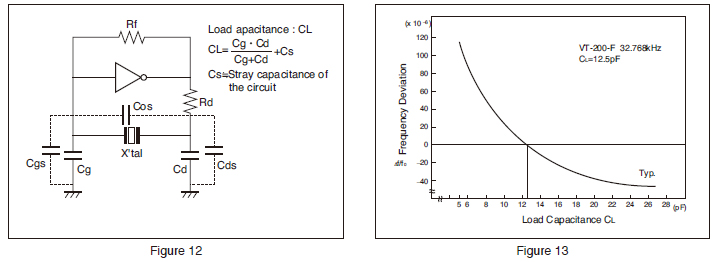
The mica capacitors, particularly C1 and C2, play a vital role in tuning the circuit. C1, with its 10 pF value, sets the base capacitance, while C2, with a higher value, allows for fine-tuning the resonant frequency. The inclusion of a trimmer capacitor (C3) provides additional flexibility in adjusting the circuit's frequency response, which is particularly useful for compensating for temperature variations or component tolerances.
The inductor L1 is carefully constructed with 8 turns of wire on a toroidal core, which helps in minimizing electromagnetic interference and improving the overall efficiency of the circuit. The tapping of 3 turns from the cold end allows for better coupling with the transistor, enhancing the gain and stability of the oscillator.
The choice of the transistor Q1 is also significant. The recommended Fairchild 2N5179 is known for its high-frequency performance and reliability. It is essential for amplifying the oscillations generated by the crystal, ensuring that the output power remains within the specified range of 5 to 15 mW.
Finally, the RFC (Radio Frequency Choke) value of 0.39 H is selected to resonate with the capacitance of the crystal holder, further stabilizing the oscillator circuit. The overall design emphasizes the importance of component selection and layout to achieve a robust and efficient oscillator circuit suitable for VHF/UHF applications.This is a circuit of 90-125 MHz Crystal which is very useful for VHF/UHF converters. This circuit provide 5 to 15 mW output. High-quality fifth- or seventh-over-tone crystal type can be used in this circuit. Undesired oscillation never reach above 500 MHz because of Ferrite bead FB. Using regulated power supply and allowing crystal to operate at i ts natural series-resonant frequency, will give best stability. Here is the schematic diagram of the circuit: The C1 is a 10pF mica. For C2, use as high value as possible such as 20 to 60pF mica. A 20 pF miniature trimmer or piston is used for C3. The value of L1 is 8 turns no 24(0. 5mm) on amidon T37-12 toroid core, tapped 3 turns fro cold end. For Q1, we can uses 2N5179, 2N2857, 2N3563m 2N918 or equivalent but fairchild 2N5179 is recommended. The value of The RFC is 0. 39 H which resonate with crystal holder capacitance. The maximum length of Y1 is 6mm or 1/4 ³. The value of Y1 is 90 to 125 MHz, 5th or 7th overtone, series-resonant, HC-18/U crystal. [Circuit`s schematic diagram source:J. Reisert, VHF/UHF Techniques, Ham Radio, March 1976, p 44-48] We aim to transmit more information by carrying articles. Please send us an E-mail to wanghuali@hqew. net within 15 days if we are involved in the problems of article content, copyright or other problems.
We will delete it soon. 🔗 External reference
Related Circuits
A crystal oscillator circuit is a straightforward oscillator circuit that can be easily understood through its schematic diagram. It serves as a replacement for a conventional oscillator network, which typically consists of an LC combination. This simplicity is also...
The drive level of a crystal unit is indicated by the operating power level or current consumption. Operating the crystal unit at excessive power levels can degrade its characteristics, potentially causing frequency instability or physical failure of the crystal...
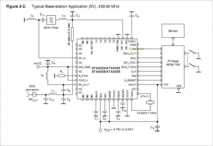
The ATA5743 is a multi-chip PLL receiver device housed in an SSO20 package. It has been specifically designed to meet the requirements of low-cost RF data transmission systems, supporting data rates ranging from 1 kBaud to 10 kBaud using...
Liquid crystal displays (LCDs) are available in various versions and sizes. The wide variety of features has led to some confusion regarding pin configurations. Consequently, even after extensive searching for a suitable screen, users often encounter difficulties in utilizing...
The Birmingham, Alabama Crystal Radio Group website serves as the host for the crystal radio receiving contest. This page provides information about the group and its activities related to crystal sets, including details about the 2008 contest radios. The Birmingham,...
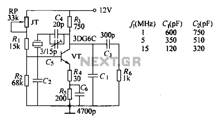
The typical crystal oscillator circuit depicted in the figure is a three-point oscillator designed for capacitance feedback. The oscillator's frequency is influenced by the series and parallel resonant frequencies of the crystal. This type of circuit is commonly known...