
Crystal display (LCD) tester
 tester")
When viewing the 'sandwich' of two glass sheets from a perpendicular angle, the conductive patterns, which are typically formed of dots, remain invisible. However, when observed from a corner, pale shadows may be distinguished. The space between the two sheets contains an organic liquid that alters its light polarization when an electric field is applied. As a result, the conductive patterns can appear either transparent or dark, depending on the applied voltage. Identifying the parts that form the digits requires an alternating voltage at specific pins.
It is crucial that the voltage is alternating rather than constant, as a constant voltage can cause irreversible damage to the screen. This damage is due to the displacement of the conductive material that forms the digits. The alternating voltage minimizes deterioration because the displacements caused by the positive and negative halves of the waveform counteract each other visually. Unfortunately, most oscillators intended for generating such waveforms do not produce 'clean' symmetrical outputs, often resulting in a rectangular waveform with a duty cycle around 50%.
The 4047 oscillator is suitable for this application as it provides the desired waveform using an internal divider, resulting in two additional outputs with a 50% duty cycle. The oscillator operates at a frequency of 1 kHz and can function with a voltage supply ranging from 3 to 9 V. Typically, a standard battery powers the oscillator, although using an adjustable laboratory power supply may yield better results for fine-tuning the voltage to optimize the screen's performance.
The current circuit draws a total of 1 mA. The control voltage should be applied between the common pin, usually the backplane pin, and the pin corresponding to the section being identified. If the backplane pin is unknown, connecting one output from the oscillator to a section and the other to the remaining pins will help identify the backplane. If the section does not respond when stimulating all other pins, it is likely that the display has two distinct backplanes, each controlling a different group of segments.
This circuit provides a systematic approach to identifying the pin configuration of LCDs, facilitating their integration into various electronic applications. By ensuring the correct voltage and waveform are applied, users can effectively utilize LCD technology without the risk of damaging the display.Liquid crystal displays are currently available in several versions and various sizes. The wide variety of features, has resulted in there a little chaos in the provision of the pin. So that even when, after much effort, we can find a screen that fits our needs, we are rather difficult to use it. And because most likely we can not find technical manuals to describe all that remains is for us to try to locate the pins by making successive trials.
For this work the circuit described below is particularly useful and convenient. An LCD consists of two thin sheets of glass are few among them. On inside surfaces of the two sheets have been developed various shapes that are electrically conductive. When looking at the 'sandwich' of two glass sheets perpendicular to the surface, the conductive patterns are, usually consist of parts or places dots are invisible.
If we look in a corner, we can distinguished as pale shadows. The gap between two sheets of an organic liquid in which when imposed electric field changes the polarization of light passing through it. In this manner the conductive patterns can appear transparent or dark, depending on whether or not they require in these voltages.
In ieriptosi we have in our hands a screen is very easy to identify the parts which form the digits of an alternating voltage of a few pins that correspond to them. It is important to be the alternating voltage is not constant, since in the latter case the screen will suffer irreparable damage.
The reason of the disaster has to do with the displacement of the conductive material forms, which as noted above aiioteloun parts of digits. The alternating voltage causes and that the same phenomenon, but the displacement caused by the positive half, called from that caused by the negative, so a visual basis of no observed deterioration.
Most of the oscillators, which could be used for producing such a waveform, is unfortunately not able to provide 'clean' symmetrical waveforms. Instead, they produce a rectangular ground time to time (DC) ranging around 50%. Contrary to these, 4047, chosen for this application, provide the requested using an internal splitter.
As a result we have two additional outputs with DC = 50%. The operating frequency of the oscillator is equal to 1 kHz, while the voltage required for operation can be any between 3-9 V. Most often, the power of the oscillator would a normal battery, but in some cases it may be better to resort to an adjustable laboratory power supply.
So, if you resort to the second option, you will also find the voltage at which the screen antspokrinetai better or the tendency that for which the angle iaratirisis is the best. The current circuit absorbs the total reaches 1 mA. The control voltage should in all cases be between the common pin, which most often is the pin backplane, and the pin corresponding to the section want to locate.
If you do not know the pin backplane, you can connect an output oscillator section, and the other to turn it the other pins. Once the department become dark, the same time you know and what is the pin backplane. If it happens and the Board does not 'tan' having stimulates all other pins, then you most likely have to display two different backplane which each can controls and a different group.
Related Circuits
Aside from the diode, which requires a PbS (Lead Sulfide) galena crystal for replacement, all components visible in the circuit for the non-powered version can be constructed using enamel wire, aluminum cooking foil, cardboard wax, and similar materials. The...
The Mini 3-digit display, also known as the "DVM-module" (digital voltmeter module), can be easily tuned and modified due to firmware control. Key advantages of this module include an internal reference voltage of 2.56V in the ATmega8 microcontroller. By...
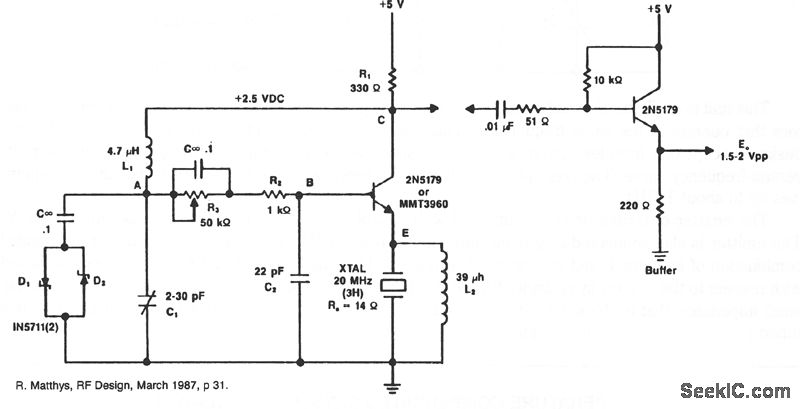
A typical circuit operating at 20 MHz is presented. The crystal, which possesses an internal series resistance (RS) of 14 ohms, oscillates at its third harmonic. Diode clamps D1 and D2 provide constant amplitude control. The transistor functions continuously...

With this simple measuring device can: Determine the Zener voltage up to 25V. The connections of cathode and anode of each diode finding. Check if a diode fails. Silicon, germanium and Schottky diodes distinguish. LED test and the V...
The device is designed as a panel meter suitable for use in DC power supplies or any application that requires accurate voltage indication. It utilizes the CL7107 integrated circuit (IC) from INTERSIL, which is housed in a 40-pin package...

This circuit performs a rapid battery test without requiring a power supply or costly moving-coil voltmeters. It features two ranges: when SW1 is configured as depicted in the circuit diagram, the device can test batteries ranging from 3V to...