
900 MHz Radio Amplifier Circuit

The 900 MHz amplifier circuit utilizing the BFG480W transistor is designed to operate efficiently within the specified frequency range, making it ideal for applications in communication systems where signal integrity is paramount. The BFG480W is a high-frequency NPN transistor known for its low noise figure and high gain, which are essential characteristics for low-noise amplification.
In this circuit, the BFG480W is typically configured in a common-emitter configuration to maximize voltage gain while maintaining stability. The input stage may include impedance matching networks to ensure optimal power transfer from the source to the amplifier. This can involve the use of inductors and capacitors to create a tuned circuit that resonates at 900 MHz.
Biasing is a critical aspect of the design to ensure the transistor operates in the linear region. Resistors are used to set the appropriate DC operating point, taking into account the supply voltage and the desired quiescent current. Capacitors may be employed for AC coupling at the input and output to block DC components while allowing AC signals to pass through.
The amplifier's output stage can also include a matching network to minimize reflections and maximize power transfer to the load. This is particularly important in RF applications, where mismatches can lead to signal degradation and reduced performance.
Overall, the design of a 900 MHz amplifier circuit using the BFG480W requires careful consideration of component values, layout, and thermal management to ensure reliable operation and optimal performance in various applications, including wireless communication and broadcasting.This 900 MHz Amplifier Circuit is built with BFG480W which has a good linearity performance. Therefore the BFG480W is well suited for LNAs with high linear.. 🔗 External reference
Related Circuits
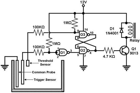
Figure 1 illustrates a circuit designed to monitor the water level in a tank and control a water pump accordingly. The primary component of the circuit is the CD-4011 Quad NAND gate, with three of its gates utilized as...
The following circuit illustrates an audio amplifier circuit diagram with a power output of 25 watts. Features include its widespread use in nearly all mass-market stereo receivers produced, providing enhanced sound quality. This audio amplifier circuit is designed to deliver...
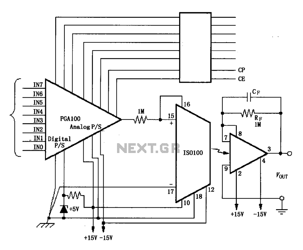
The ISO100 multichannel data acquisition system comprises a programmable gain amplifier isolated by an optocoupler, a programmable amplifier (PGA100), and an isolation amplifier (ISO100). The optocoupler selects three channels and is coupled to the programmable gain amplifier, which can...
The 27MHz quartz crystal oscillator circuit is illustrated in figure 1. The biasing circuit consists of resistors R1, R2, and R3, while C6 serves as the bypass capacitor. The partial voltage circuit includes capacitors C1, C2, C3, and C4...
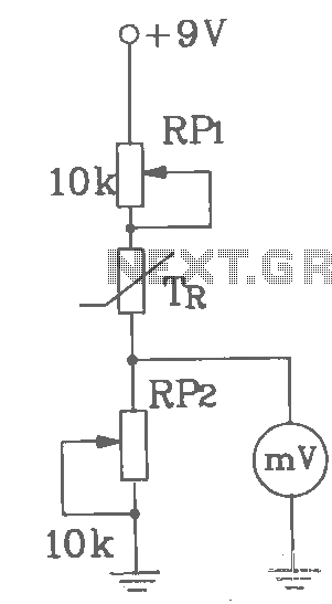
T-121 temperature sensor electronic thermometer circuit diagram shown below The T-121 temperature sensor circuit is designed to measure and display temperature readings accurately. The circuit typically consists of a temperature sensor, such as the T-121, which converts temperature variations into...
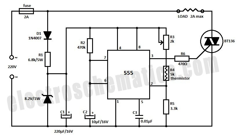
Construct a temperature controller circuit using the 555 integrated circuit (IC) in combination with a thermistor resistor divider. The benefit of this design is that it does not require a well-regulated power supply. The resistor divider network comprises an...