
Temperature Controller with 555 Circuit

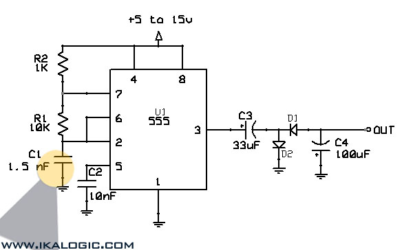
The temperature controller circuit leverages the 555 timer IC, which operates in monostable mode to regulate the heating element based on the temperature readings from the thermistor. The thermistor's resistance decreases with an increase in temperature, creating a voltage divider with resistors R3 and R5. The adjustable resistor R3 allows for fine-tuning of the temperature set point, providing flexibility in the system's operation.
In this configuration, the 555 timer's pin 2 serves as the trigger input, which responds to the voltage level determined by the thermistor and the resistors. When the thermistor detects a temperature below the set threshold, the voltage at pin 2 drops, triggering the 555 timer. The timer's output at pin 3 goes high, activating the triac that controls the power to the heater. This action initiates the heating process.
The timing cycle duration is determined by the external components connected to the 555 timer, typically involving resistors and capacitors that set the timing interval. If the thermistor detects a temperature rise above the set point during this timing period, the circuit is designed to cut power to the heater at the end of the timing cycle, preventing overheating. Conversely, if the temperature does not exceed the threshold, the heater remains energized until the timing cycle concludes.
This circuit design is particularly advantageous for applications where a stable power supply is not feasible, as it operates effectively with a wide range of input voltages. Overall, the 555-based temperature controller provides a simple yet effective solution for temperature regulation in various electronic and heating applications.Build a temperature controller circuit with the 555 IC together with a thermistor resistor divider. The advantage is that a well regulated power supply is not needed. The dividing network consists of adjustable resistor R3, thermistor R4 and R5. When the thermistor temperature is below a set value the voltage at pin 2 of the 555 drops belo w 1/3 of Vcc. This turns on the triac controlled heater and also starts the timing cycle. If the thermistor temperature rises above the set point before the end of the timing cycle the heater shuts off at the end of the timing period. Otherwise the heater continues to stay on. 🔗 External reference
Related Circuits
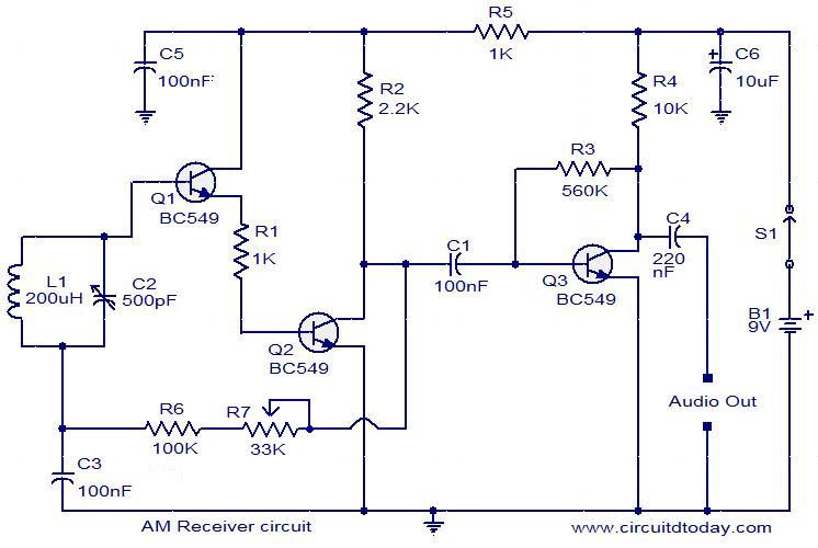
The following circuit illustrates an AM receiver capable of operating within the frequency range of 550 to 1100 KHz. Features include adjustments for sensitivity and selectivity of the circuit. The AM receiver circuit designed for the frequency range of 550...
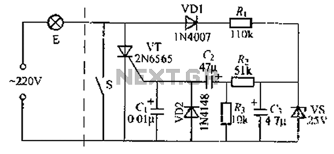
A delay circuit using an improved quenching lamp pull switch is described, focusing on its performance and the delay function in lighting control. The circuit exhibits a high degree of stability and reliability. When switch S is closed, the...
This is a simple and cost-effective inverter designed to power a small soldering iron (25W, 35W, etc.) in situations where a mains supply is unavailable. The circuit utilizes eight transistors. The inverter circuit operates by converting DC voltage from a...
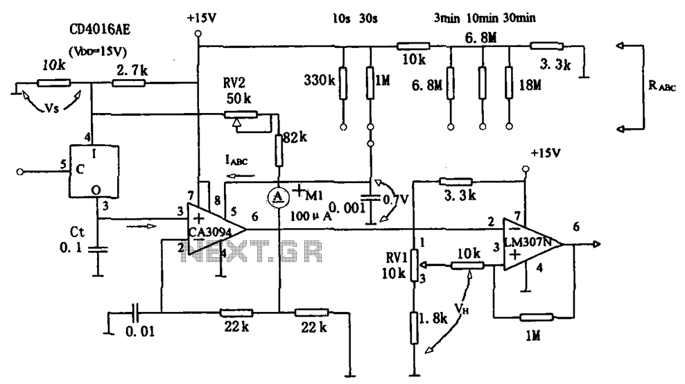
The long timer circuit utilizes an operational amplifier, specifically the CA3094, to control the discharge formula for extended timing. This is typically achieved by adjusting the variable resistor RV1, which alters the timing duration to meet specific requirements. The long...
This circuit converts a positive voltage to a negative voltage, resulting in a loss of approximately 1.5 V. For instance, supplying 9 V to the circuit yields an output of -7.5 V. Additionally, this circuit can function as a...
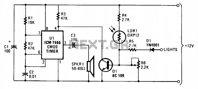
As dusk begins to fall, the sensor, which is a cadmium-sulfide light-dependent resistor (LDR), activates a small horn to provide an audible reminder to turn on the lights. The circuit can be turned off by simply switching on the...