
915MHz Power Amplifier RF2155 circuit diagram

The RF2155 power amplifier circuit is designed for efficient amplification of 915MHz RF signals, making it suitable for various wireless communication applications. The architecture incorporates a preamplifier to enhance the input signal before it reaches the power amplifier stage, ensuring optimal performance and signal integrity. The choice of gain settings allows for flexibility in applications requiring different output power levels, accommodating various operational environments.
The circuit's design includes critical components such as UHF blocking capacitors and a secondary harmonic filter, which are essential for maintaining signal quality by minimizing unwanted harmonics that could interfere with the desired RF signal. The use of transmission lines in the harmonic filter design is a common practice, as it offers a compact solution for filtering while maintaining the necessary inductance and capacitance values.
Power control features are integrated into the design, allowing for dynamic adjustment of the amplifier's operational state based on the voltage applied to pin 8. This capability is particularly useful in battery-operated devices, where power conservation is a priority. The gain control terminals at pins 15 and 16 provide additional versatility, enabling precise control over the output power levels, which can be critical in applications where signal strength must be carefully managed.
Overall, the RF2155 power amplifier circuit is a well-engineered solution for RF amplification, combining flexibility, efficiency, and effective harmonic management, making it suitable for a range of 915MHz applications. As shown in FIG constituted by 915MHz RF2155 power amplifier application circuit. Radio frequency (RF) signal from the input pin 7, after the preamplifier, after the last stage power amplifier output is amplified by 11 feet. 7 feet and the internal amplifier is directly coupled, it is proposed in 7 feet plus a UHF blocking coupling capacitors. Since there are four possible gain settings, so a series with the input 6.8nH inductance. Final PA is a mismatch collector transistor output terminal 11 feet and 14 feet are connected inside the chip, 14 feet as the final stage amplifier power supply terminal, providing a bias current through these pins to the final amplifier.
14 feet as a secondary harmonic filter circuit, effectively shorting the second harmonic, using transmission lines as about 500mils inductance and 33pF capacitance of the filter (near Vcc may be placed at a tantalum capacitor). 8 feet to power control pin (PC), you can control the pin voltage to control the power supply. When the voltage is low (0V), the amplifier power supply is turned off; when the voltage is high (3V), the amplifier is in full power operation.
8-pin external UHF or HF filter capacitor. 15 and 16 feet for the RF power gain control terminal, control the output power gain of 8dB bit step and 16dB bit step, these feet high at least 2.7V, shall not exceed 3.3V, while an external UHF bypass capacitor.
Related Circuits
This system is designed to communicate or transmit a text message from one location to another using a wireless circuit. The text message is encrypted with a microcontroller, and the encrypted message is transmitted wirelessly. At the receiving end,...
The file being accessed no longer exists. It may have been renamed or removed from the archive. Navigation links are available on the left to browse the desired area of the archive. The connection is to cdn.preterhuman.net, which mirrors...
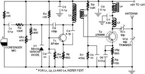
Clearly indicate on the circuit diagram each type and size of the components. There is a need for assistance in designing a low power FM transmitter circuit, specifically using the BA1404 FM transmitter with a center frequency of 79W...
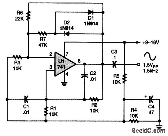
A 741 operational amplifier is configured within a Wien-bridge audio sine-wave oscillator circuit. The components C1, C2, R1, and R2 are responsible for determining the operating frequency of the circuit. By utilizing NPO capacitors and metal-film resistors, the oscillator...
Introduction The MIC2290 is an internally compensated standard step-up switching regulator that features an integrated power switch and Schottky diode. The inclusion of these components makes the MIC2290 an optimal solution for 48V Avalanche Photo Diode (APD) applications. In...
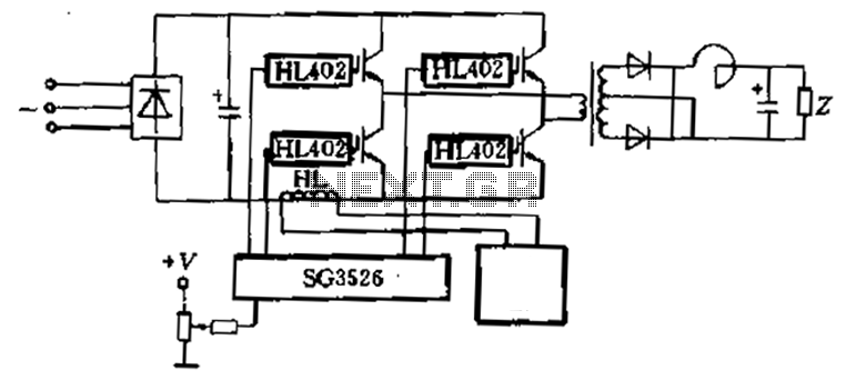
Applications are provided to complete the four-piece HL402 switching power supply system diagram, which drives four power IGBT switching power supplies. The IGBT drive pulse is generated by the SG3526. The HL component serves as a current sensor, utilized...