
transmitter circuit diagram

The circuit design for the BA1404 FM transmitter is a robust solution for amateur radio enthusiasts seeking to create a low-power FM transmission system. The BA1404 integrated circuit (IC) is specifically designed for FM transmission applications and offers high integration, which minimizes the need for additional components. The device operates effectively within a wide supply voltage range, making it suitable for various amateur radio setups.
The schematic should clearly label each component, including resistors, capacitors, transistors, and connectors, ensuring that the specifications for each part type and size are easily identifiable. The BA1404's pin configuration allows for straightforward connections to external components, facilitating the integration of a microphone for audio input as well as a line-level audio source.
The transmitter circuit utilizes a modulation technique that combines both microphone and line input signals, which are amplified and mixed before being fed into the modulation stage. The circuit includes a negative feedback mechanism to stabilize the amplification process, which is critical for maintaining signal integrity. The output stage is designed to drive an antenna, achieving a transmission range of approximately 1000 meters under optimal conditions.
For the output amplification, it is recommended to use transistors with appropriate specifications that can handle the frequency and power requirements without overheating. The suggested alternatives, such as 3DG130C or 3DG12C, provide better thermal management compared to the originally specified 2SC8050, which is prone to excessive power consumption and thermal failure.
Incorporating a modulation monitor circuit allows the user to observe the modulation depth and ensure that the transmitter operates within acceptable parameters. The overall design aims to provide a user-friendly experience for setting up a small FM radio station, with the potential for coverage extending up to 500 meters, depending on environmental factors and antenna characteristics.
In conclusion, the BA1404 FM transmitter circuit is a practical and efficient solution for those interested in amateur radio transmission, combining simplicity with effective performance. Proper attention to component selection and circuit layout will enhance the reliability and functionality of the transmitter.Be sure to mark clearly on the circuit diagram of a part of each type and size! Thank you! Satisfied with the answer, and additional! Do not tell me there are very general site, so I am looking for. Thank you, brothers and sisters, brothers and sisters, aunts and uncles who, thank you! Best answer I have ah, but you point too, do not give! Help me answer time of | to the TA for helpParticipate in activities: No content to participate in activities related to low power FM transmitter FM transmitter circuit 10 how to pick the week friends who know FM transmitters Instant answers! ! ! help you design a master with the BA1404 FM transmitter center frequency 79W, the radius of 4K. Thank you! 1 want to buy a small TV, a small FM transmitter, the old point does not matter, cheap, good credit important.
One more question See the problem with the theme: FM transmitter circuit diagram to answer a total of one other FM Transmitter - whole solid-state design. Final stage LDMOS power amplifier module from the synthesis, high efficiency, large power surplus, air missile integration of active radar transmitter In this paper, we show a kind of a small core BA1404 FM stereo transmitter, a lot of friends because he is very keen, and it asked me the information, so put put it up.
In fact, in many applications on the BA1404 electronic magazines and newspapers more than a briefing, not really nothing new, but he really practical. ROHM BA1404 produced by the U. S. FM radio transmitter ASIC; its high integration; required external components; work reliably; supply voltage to adapt to wide range of work was still as low as 1.
5V, making it suitable for amateur conditions a variety of radio transmitting devices. Since I no scanner, we can only draw in PROTEL in a typical circuit in the painting in the WORD of its internal functional block diagram and pin description of plans to introduce, said the circuit with high sensitivity FM radio range can reach 1000 meters, you can go to trial, as shown in Figure one. Internal structure and the pin is shown in Figure II. In particular 38KHz crystal cross hard to find, can balance the capacitance of a 57P 5, 6 feet circuit can replace the work between the only D effect is not too obvious too!
You can make with his own small sound of a radio station it! * Note that the original rate transistor amplifier stage used for the 2SC8050 2SC8050 fact we all know about the maximum frequency of 100MHz, where use is inappropriate, due to excessive power consumption and a sharp fever, and in short time to burn, it is better to use such domestic 3DG130C or 3DG12C be made of the heat pipe caps * rate a better performance, such as the use of Taiwan`s D40, D50 and other specialized launch tubes would be better if just need a fresh point of work adjustment. Note: Due to my negligence not connected to the power amplifier stage, T1 should be connected to the upper end of 4.
5-6V power supply circuit on the basis of the last increase in the output filter circuit, the circuit is more perfect, the frequency performance is better. FM transmitter works with the circuit from the full requirements of the launch, but also while using a microphone and line input sound signal, the background voice.
Modulation monitor circuit also joined the header in order to better understand and use well the transmitter, the circuit as shown, a brief introduction, whether they think it is like a radio station equipment as many functions. Yes, it sets a small transmitter can help you to easily set up an FM radio amateur! Coverage in the 500M or so. Intake to the microphone signal, the C1 coupling into the BG1 and external circuit voltage negative feedback single-tube amplifiers, to amplify the weak voltage signal amplitude and U1A enough amplified with the line input signal is mixed into the U1B.
Mixed signals all the way through R17 to the modulation and around the BG2 FET test circuit compose 🔗 External reference
Related Circuits
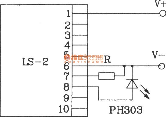
The LS-2 remote control switch infrared sensor module is similar to the LS-18 but functions as a reflector. The LS-2 pin diagram and internal block diagram provide insights into its electrical parameters. The operating voltage for the LS-2 remote...
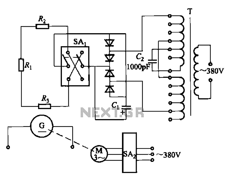
The AR-300 DC arc welding machine circuit includes the AX, AX1, AX3, and AR series. The structure of these machines is fundamentally similar, consisting of a three-integral unit converter, a phase asynchronous motor, and a DC arc welding generator...
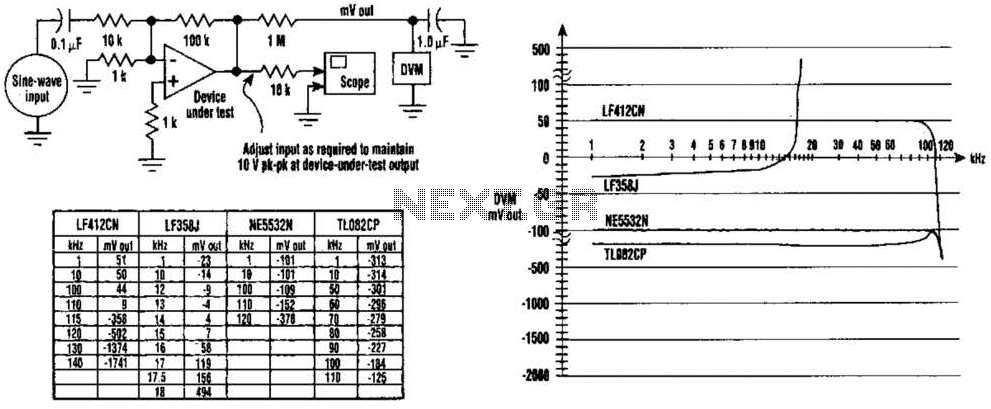
The DC values of op-amp offsets cannot always be assumed to remain constant when delivering AC outputs. No device is perfectly symmetrical in terms of maximum positive slew rate compared to maximum negative slew rate. As a result, there...
The protection circuit output amplifiers and speakers has some interesting features such as isolating the speaker from the amplifier output when shown a continuous trend in output or when the temperature gets too much cooler while providing a time...
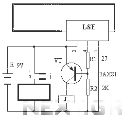
The circuit operation principle of the device illustrated in Figure 13 is as follows: When the barbed wire (Fe) remains intact, the output pin (O) of the LSE is at a high state. Consequently, the transistor (VT) remains off,...
This is a classic design of a 35 W final amplifier utilizing two EL34 tubes in a push-pull configuration, developed by Siemens and Halske. The design dates back to March 24, 1953, and is identified by the code SV410/1....