
9V NiCd battery charger

The described circuit operates by utilizing a basic charging topology suitable for NiCd batteries, which are known for their robustness and ability to deliver high discharge rates. The circuit includes a power supply unit that provides the necessary voltage and current to charge the batteries. The four battery slots are connected in parallel, allowing them to be charged simultaneously while ensuring that each battery receives the appropriate voltage.
The potentiometer P1 serves as a variable resistor, enabling the user to adjust the output voltage to match the specific requirements of the NiCd batteries being charged. This feature is critical, as charging voltages must be carefully controlled to prevent overcharging, which can lead to reduced battery life or even damage.
In addition to the charging mechanism, the circuit may incorporate various safety features, such as overcurrent protection, thermal cutoff, and possibly a LED indicator to signal when charging is in progress. These enhancements improve the reliability and safety of the charging process, making it suitable for both personal and professional applications.
Overall, the circuit diagram provides a clear and effective solution for charging multiple NiCd batteries, ensuring that they are charged efficiently and safely.Using this electronic circuit diagram can be designed a very simple charging circuit for NiCd batteries. This electronic charger allows simultaneous charge of four NiCd batteries of 9 V, cursor of P1potentiometer set voltage that will used..
🔗 External reference
Related Circuits
The circuit described is suitable for indicating the capacity of a battery using a low-cost electric clock. By connecting a resistor across the battery terminals, the battery discharges at a faster rate than it would with the clock alone....
This design integrates power-on and low-battery indication features, capable of operating with any battery voltage up to 15V. It exhibits a very low current drain of 2mA or less. The circuit design incorporates a power-on indicator that activates when the...
The Accu charger circuit is straightforward and simple to construct, requiring no more than ten components. In addition to its ease of assembly, this charger circuit is also cost-effective and highly efficient. The circuit requires a power supply from...
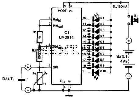
The LM3914A bar graph LED is utilized as a voltmeter for testing batteries. This circuit operates on a 4.5-V battery and compares the battery under test with an internally generated reference, established by resistors R1, R2, and potentiometer P1....
A 12V battery is charged using a solar panel. When the battery reaches 12V, the solar panel is disconnected from the battery, and the load is connected to the battery. The solar panel is reconnected to the battery when...
The following diagram represents the schematic of a Ni-CAD battery charger circuit, which features current and voltage limiting to prolong the battery's lifespan. The lamp L1 will illuminate brightly while the LED will be off when the battery is...