
simple accu charger circuit

The Accu charger circuit's design typically includes a transformer, a rectifier, a filter capacitor, and a voltage regulator, along with additional components such as resistors and diodes to ensure proper operation. The transformer is essential for reducing the high voltage AC supply to a safer level suitable for charging batteries. The output from the transformer is then fed into a full-wave rectifier, which converts the AC voltage to DC voltage.
Following rectification, a smoothing capacitor is used to filter out any ripple in the DC output, resulting in a more stable voltage that can be used to charge the battery without causing damage. A voltage regulator may also be included to maintain a consistent output voltage, ensuring that the battery is charged efficiently and safely.
Additional components, such as protection diodes, can be added to prevent reverse polarity, which could potentially damage the circuit or the battery. The overall design emphasizes efficiency and simplicity, making it an ideal solution for basic battery charging needs. This circuit is particularly suitable for applications where cost and ease of use are critical, such as in small battery-operated devices or backup power supplies.The Accu charger circuit is very simple and easy to make, because it only requires a few components are also not more than 10 components. Besides easy charger circuit is also very cheap and very efficient. This circuit requires power supply from a transformer that comes from an AC voltage 220 and diuturunkan be 12-13 volts and then enter to-circuit an
d 12 Volt DC output allows for charging 12V battery 🔗 External reference
Related Circuits
The Wien-Bridge oscillator meets specific requirements due to the presence of a low-pass filter, a high-pass filter, and a 180-degree phase shift from the feedback networks connecting the input to the output. This configuration results in a total phase...
The circuit serves as a foundational design, requiring experimentation for specific applications. In popular microwave bands, local oscillators (LOs) are typically generated using overtone crystal oscillators followed by multipliers. A table presents the standard LO frequencies for narrowband segments,...
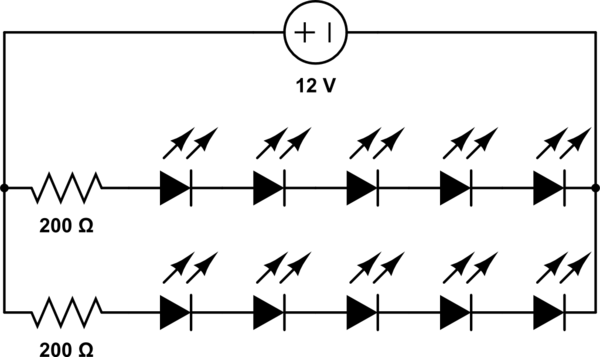
A 12V power supply is available, and there is a need to power LEDs with a forward voltage of 2V. It is questioned whether only six LEDs can be powered or if the cathode of one LED can be...

The Quick and Easy Wireless circuit is not overly complex, but it requires careful verification of connections before initial operation. Key components in the circuit include the 7805 voltage regulator, the 18F452 microcontroller, an RC Receiver, and an RC...
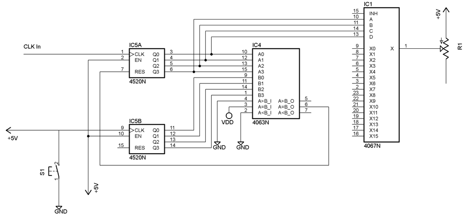
The following video showcases a test circuit of a 16-step analog sequencer based on Mauno Tuominen's schematic for an analog CMOS sequencer utilizing a 4067N multiplexer/demultiplexer. A DIY version of the sequencer can be found at studiomanus.com. An old...
This circuit generates the power required to operate a bipolar stepper motor. It allows for adjustments in both the rotation speed and direction of the motor. The design includes two integrator circuits (A1, A3) and an amplifier (A2) connected...