
Police siren using NE555

The described circuit utilizes the NE555 timer IC in a dual configuration to create a police siren sound. The first timer, IC1, operates as a slow astable multivibrator, generating a low-frequency square wave at approximately 20Hz. This frequency is suitable for producing a slow, wailing sound characteristic of a police siren. The duty cycle of 50% ensures that the high and low states of the output waveform are equal, contributing to a balanced sound output.
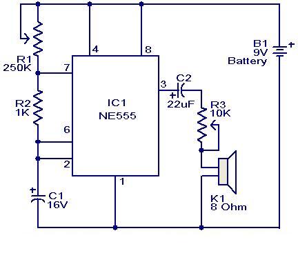
IC2, the second timer, is configured as a fast astable multivibrator, generating a higher frequency square wave at around 600Hz. This high-frequency signal is essential for adding a rapid modulation effect to the siren sound. The output from IC1 is fed into the control voltage input (pin 5) of IC2, allowing the slower frequency of IC1 to modulate the faster frequency of IC2. This interaction results in a dynamic sound that simulates the rising and falling pitch of a siren.
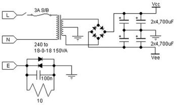
The power supply for this circuit can vary between 6V and 15V DC, making it versatile for different applications. The output can be further amplified by connecting an external power amplifier, which enhances the loudness of the siren effect, making it more suitable for practical use in alarm systems or other signaling applications.
For individuals seeking to deepen their understanding of the NE555 timer IC, a selection of three recommended books is available for purchase online. These resources provide comprehensive insights into the operation, applications, and various projects involving the NE555 timer, catering to both beginners and advanced users.A lot of electronic circuits using NE555 timer IC are already published here and this is just another one. Here is the circuit diagram of a police siren based on NE55 timer IC. The circuit uses two NE555 timers ICs and each of them are wired as astable multivibrators. The circuit can be powered from anything between 6 to 15V DC and is fairly loud. By connecting an additional power amplifier at the output you can further increase the loudness. IC1 is wired as a slow astable multivibrator operating at around 20Hz @ 50% duty cycle and IC2 is wired as fast astable multivibrator operating at around 600Hz. The output of first astable mutivibrator is connected to the control voltage input (pin5) of IC2. This makes the output of IC2 modulated by the output frequency of IC1, giving a siren effect. In simple words, the output frequency of IC2 is controlled by the output of IC1. For all of you who do not have a clear understanding of the working and basics of the NE555IC, we have provided an online book store for you.
Here 3 books are reviewed in detail with links to buy the books online itself. Get your copy now by clicking here:- 3 Great Books to Learn 555 Timer Circuits and Projects 🔗 External reference
Related Circuits
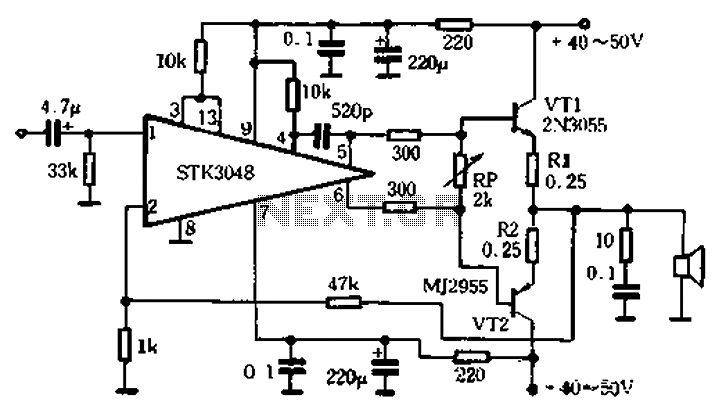
The circuit utilizes the high-power complementary tube STK3048, which operates at high voltage and offers a wide dynamic range. It features an accurate differential input pair, with a common emitter configuration and output terminals connected to a collector constant...
For hobbyists or professional electronic engineers engaged in various electronic experiments, troubleshooting, or testing, it is essential to provide a wide range of variable options. In electronic engineering, the ability to manipulate and measure a wide range of variables is...
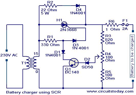
A simple battery charger based on SCR is presented. The SCR rectifies the AC mains voltage to charge the battery. When the battery connected to the charger is discharged, the battery voltage decreases, inhibiting the forward bias voltage from...
This weblog focuses on electronic circuit schematics, PCB design, DIY kits, and diagrams for electronic projects. A simple circuit utilizing the NE555 IC is presented, which can be employed to generate metronomes. This circuit is particularly beneficial for music...
A 30W Class AB power amplifier circuit diagram utilizes a power transistor. To set up the amplifier, adjust the variable resistor R1 to its maximum value and R12 to zero. After completing this setup, activate the amplifier. Adjust R1...
The requirement was to add a digital readout to a manually operated bend roller machine to accurately monitor the amount of material fed into the machine. The readout should be user-friendly, requiring no setup other than initial calibration, and...