
battery charger circuits

The collection of battery charger circuit schematics encompasses a diverse range of designs suitable for various battery chemistries and power ratings. The circuits are designed for charging capacities ranging from 5 watts to 200 watts, accommodating different types of batteries including Nickel-Cadmium (NiCd), Nickel-Metal Hydride (NiMH), Lead-Acid, Lithium-Ion (Li-Ion), Lithium Polymer (Li-Po), and Lithium Iron Phosphate (LiFePO4).
Each schematic is tailored to the specific requirements of the battery type, ensuring optimal charging efficiency and safety. For instance, NiCd and NiMH batteries typically require a constant current charging method with temperature compensation to prevent overcharging, while Lead-Acid batteries often utilize a two-stage charging process involving bulk and float charge phases. Li-Ion and Li-Po batteries require precise voltage regulation and current limiting to prevent damage, necessitating the incorporation of specialized charging ICs that manage the charging cycle effectively.
The provided schematics include essential components such as voltage regulators, current sensors, and protection circuitry to safeguard against overcurrent and short circuits. Additionally, some designs may feature microcontroller integration for enhanced functionality, such as programmable charging profiles or communication interfaces for monitoring and diagnostics.
This comprehensive array of charger circuits serves as a valuable resource for engineers and hobbyists alike, facilitating informed decisions regarding charger selection and implementation while promoting a deeper understanding of battery management systems.Here we provided several schematic drawings of battery charger circuit. These circuits covered 5W~200W NiCd, NIMH, Lead-Acid, and Li-Ion/Polymer, LiFePo4 battery packs. We hope chargers circuits files can help our users to select correct chargers also can help them to get a good understanding about our products. 🔗 External reference
Related Circuits
Traditional guitar amplifier tubes, such as the 12AX7, utilize indirectly-heated cathodes. In this configuration, the heating filament is electrically isolated from the cathode, which emits signal-producing electrons. This design simplifies the circuit significantly, allowing the cathode voltage to be...
Charging the battery in a slow manner (using a low charging current over an extended period) is the most economical and safest method. The design of the trickle charger should focus on two key points: firstly, the use of...
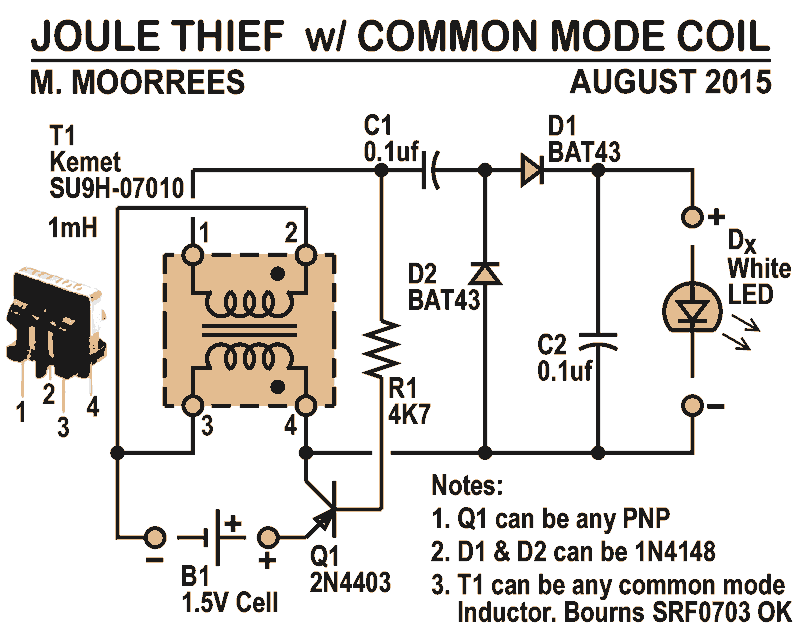
Like all joule thieves, this circuit boosts the voltage from a single 1.5V dry cell battery high enough to illuminate ultrabright GaN blue, green, or white LEDs. Instead of requiring a custom coil, it utilizes an off-the-shelf standard Kemet...
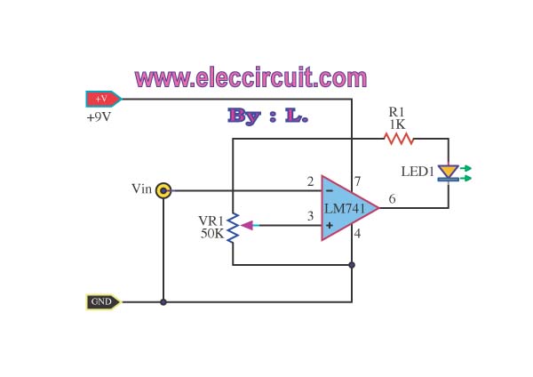
This simple low voltage tester circuit can be used to monitor batteries and other voltage sources for issues, utilizing an LED display and alarm sound. The low voltage tester circuit is designed to provide a reliable method for monitoring the...
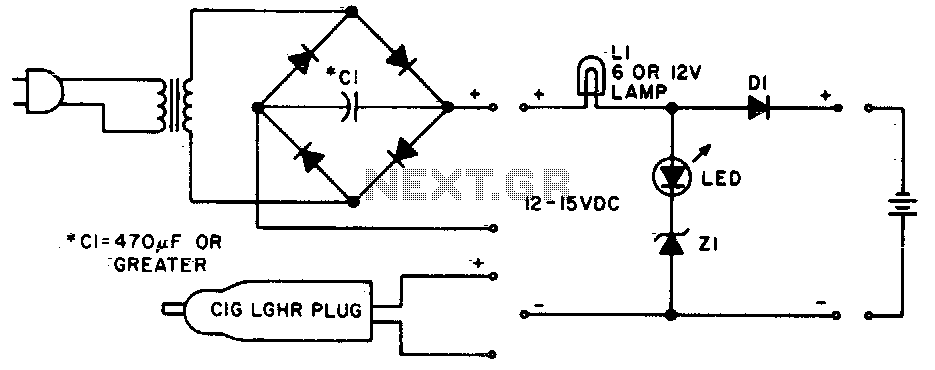
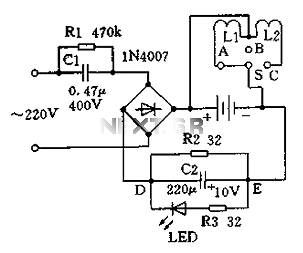
Lamp LI will glow brightly while the LED remains off when the battery is low and charging. Conversely, the LED will illuminate brightly, and the light bulb will be dim when the battery is nearly charged. Lamp LI should...
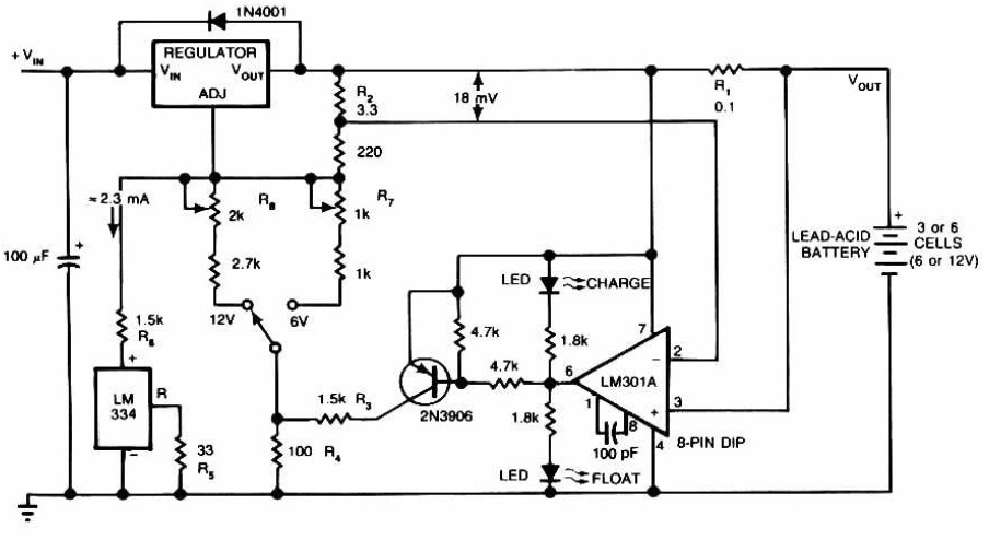
Lead-Acid Battery Charger circuit diagram. The LM301A compares the voltage drop across R1 with an 18 mV reference set by R2. The comparator's output controls the voltage regulator, forcing it to produce the lower float voltage when the battery-charging...