
A 20-kHz Third-Order Low-Pass Filter

The third-order low pass filter is designed to attenuate high-frequency signals while allowing low-frequency signals to pass through with minimal loss. The specified corner frequency of 20 kHz indicates the point at which the output signal power drops to half of the input signal power, corresponding to a -3 dB point in the frequency response.
The circuit typically consists of resistors and capacitors arranged in a specific configuration to achieve the desired filtering characteristics. In a third-order configuration, three reactive elements are utilized. This can be achieved through various configurations, such as using a combination of RC (resistor-capacitor) or RLC (resistor-inductor-capacitor) elements.
For a standard RC low pass filter, the components can be arranged in either a passive or active configuration. A passive third-order low pass filter can be constructed using three capacitors and two resistors, or alternatively, using two capacitors and one resistor in conjunction with an operational amplifier to create an active filter.
In terms of component values, the selection of resistors and capacitors will directly influence the corner frequency and the roll-off rate of the filter. The roll-off rate for a third-order filter is -60 dB/decade, meaning that for every tenfold increase in frequency beyond the corner frequency, the output signal will decrease by 60 dB.
The design also requires careful consideration of the load impedance and the source impedance to ensure optimal performance. Additionally, attention must be paid to the layout of the circuit to minimize parasitic capacitance and inductance, which can adversely affect the filter's performance.
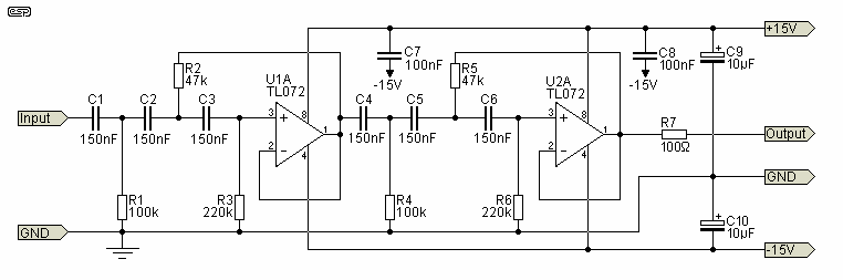
In summary, the third-order low pass filter with a corner frequency of 20 kHz is a critical component in various electronic applications, providing effective signal conditioning by filtering out unwanted high-frequency noise while preserving the integrity of lower frequency signals.This is a third order low pass filter that has corner frequency of 20kHz. It is twice as high as the auto-zero clock frequency. Here is the circuit : The input.. 🔗 External reference
Related Circuits
The purpose is supposedly to account for the fact that human hearing is less sensitive at low and high frequencies than in the upper midrange, and that this variation is dependent upon the sound intensity (SPL). The Fletcher-Munson curve...
The circuit shown is completely conventional. The Q of the filters has been optimized to allow a higher input impedance than would otherwise be possible, with the final Q of the two filters being almost exactly 0.707 (i.e., a...
The Software Defined Radio (SDR) hardware, in its most basic configuration, includes a wideband switched balanced mixer and a low noise LF amplifier. This straightforward hardware demonstrates remarkable sensitivity and linearity, making it suitable for both testing and regular...

This design circuit functions to filter out interference signals, ensuring that the signal received from a Morse code station is distinct. The circuit utilizes the earliest mode of radio communications, which employs Morse Code on a continuous wave carrier...
The low-pass Sallen-Key filter is a staple for designers because it contains few components. By redesigning the filter, a current-to-voltage conversion can be avoided when the input signal to be filtered is in current form. The Sallen-Key filter is a...
The notch filter can be integrated into nearly any receiver to attenuate a specific frequency by over 30 dB. This filter is particularly useful for diminishing heterodynes and whistles. A notch filter, also known as a band-stop filter, is designed...