
Subsonic audio Filter

The phase response is as one would expect for any filter, but it is important to note that unless the full-range signal is filtered, there may be unacceptable phase variations in the low frequency regions. Ideally, this filter should not be used in series with the sub-woofer amp, as the phase relationship between the main speakers and sub-woofer will be affected. However, it is probable that there will be no audible anomalies even if the P99 is installed in the subwoofer signal path. A power supply ground connection is necessary. The use of a PCB is recommended, as it simplifies the wiring process. Higher quality op-amps than the suggested TL072 dual versions may be used, with noise being the most critical parameter. Since the op-amps are wired as unity gain buffers, the upper frequency response will be well extended to beyond audibility.
Only a single channel is shown in the schematic, while the second channel utilizes the remaining op-amp in each of the dual packages. It is imperative that this circuit is driven from a low impedance source. The actual input impedance is greater than 47k at all frequencies, but the source impedance should ideally be no more than 100 ohms, although even a source impedance as high as 10k will cause few problems. If the full-range signal is to be passed through the filter, high-quality op-amps are recommended to prevent noise or distortion in the main signal. A switch may be incorporated to bypass the circuit when not in use. The use of a subsonic filter is not limited to vinyl discs; many CD recordings also contain subsonic energy, either deliberately or inadvertently.The circuit shown is completely conventional. The Q of the filters has been optimised to allow a higher input impedance than would otherwise be possible, with the final Q of the two filters being almost exactly 0.707 (i.e. a traditional Butterworth filter). Although in theory the tolerance of both resistors and capacitors should be 1% or better, in reality it is not that important.
1% metal film resistors are recommended (as always) but only for lowest noise, and capacitors are standard (i.e. 5% or 10%) tolerance. Yes, this will cause the response to deviate from that shown below (see Figure 2), but compared to other errors in the system (recording EQ, room LF node problems, etc.) these may be considered minor.
At least one circuit that the I know of uses a method of summing the channels below 140Hz, and although this is effective in removing the low frequency rumble (or sub-rumble in this case) component, it causes frequency response aberrations that (IMO) are not acceptable. The subsonic frequencies generated by record warp are by nature out of phase. The mono component of a vinyl disc is lateral, whereas warp signals are vertical. Stereo signals are at 45° The summing method was examined in great detail before deciding that it should not be used if the overall frequency response of the disc is to be preserved.
Frequencies below 20Hz are usually not able to be reproduced, and with the exception of synthesisers and pipe organs, are not a wanted part of the audio spectrum. This is especially troublesome with phono systems, since many of the vinyl discs you treasure (or wish to transcribe to CD) will be warped to some degree.
Any warp in a vinyl disc will cause large outputs in the subsonic region, typically well below 20Hz. For example, a 33 1/3 RPM album with a single warped section will create a signal in the pickup at 0.55 Hz (33.3 RPM / 60 = 0.555 Hz). This is a signal that will cause significant cone movement, but is undesirable in the extreme. Not only will vented subs be completely unable to handle such a signal linearly, but sealed subs will also be stressed.
As can be seen from the above, below 2Hz the overall response is better than 90dB below the passband level - nominally anything below 17Hz is effectively disappeared. There is no reason to try to better this, as it already exceeds the resolution of any digital format, and places all typical warp signals well below audibility or danger level for a sub-woofer.
The phase response is as one would expect for any filter, but it is important to note that unless the full-range signal is filtered, there may be unacceptable phase variations in the low frequency regions. Ideally, this filter should not be used in series with the sub-woofer amp, as the phase relationship between the main speakers and sub-woofer will be affected.
However, it is probable that there will be no audible anomalies even if the P99 is installed in the subwoofer signal path. wer supply ground connection. Naturally, I recommend that you use the PCB, as it makes a somewhat tedious wiring exercise very simple.
You may (as always) use better opamps than the TL072 dual versions suggested, and the most important parameter is noise. Since the opamps are wired as unity gain buffers, upper frequency response will be well extended to beyond audibility.
Only a single channel is shown in Figure 1, the second channel uses the remaining opamp in each of the dual packages. It is imperative that this circuit is driven from a low impedance. The actual input impedance is greater than 47k at all frequencies, but the source impedance should ideally be no more than 100 ohms or so (although as noted above, even as high as 10k will cause few problems).
If the full range signal is going to be passed through the filter, it is recommended that high quality opamps be used to prevent noise or distortion in the main signal. If desired, a switch may be used to bypass the circuit when not in use. The use of a subsonic filter is not reserved for vinyl discs - many CD recordings also contain subsonic energy as well, either deliberately or by accident!
🔗 External reference
Related Circuits
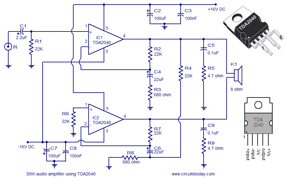
The individual is new to electronics but enjoys experimentation. They plan to create a small guitar amplifier based on a 30 Watt design, specifically the single 12VDC version referenced in comments. The intention is to incorporate a preamplifier to...
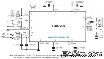
The IC TDA7295 is a monolithic integrated circuit designed for use as an audio class AB amplifier in high-fidelity applications, including home theaters and high-end televisions. The TDA7295 is a versatile audio amplifier that delivers high-quality sound reproduction, making it...

An audio power amplifier circuit for a 3-watt stereo amplifier using the MAX 7910 IC is explained below. The audio power amplifier circuit utilizing the MAX 7910 IC is designed to deliver a maximum output power of 3 watts per...
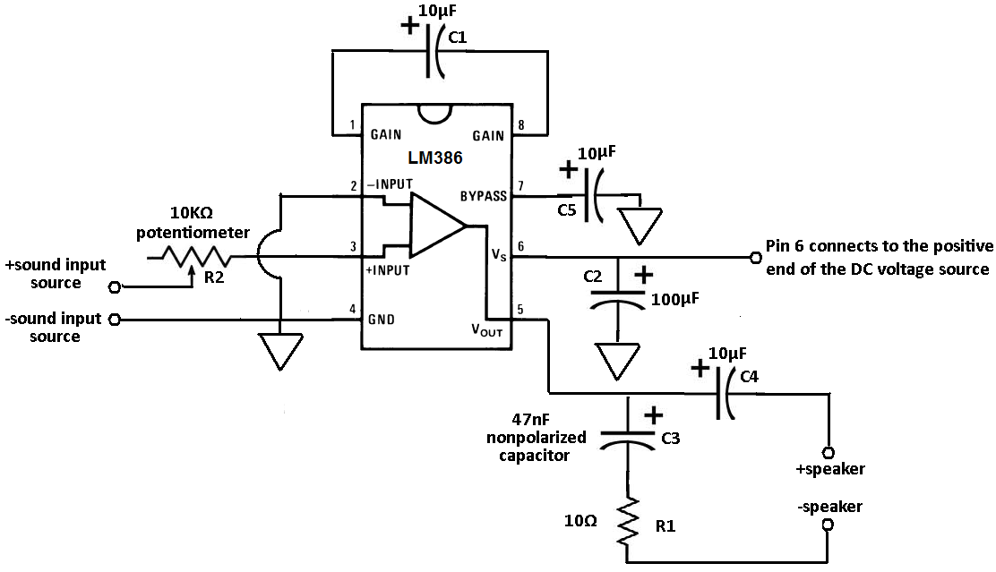
Terminals 1 and 8 serve as the gain control for the amplifier. Adjustments to the gain can be made by connecting a resistor and capacitor, or just a capacitor, between these terminals. In this circuit, a 10 µF capacitor...
This low-cost project enables audio reproduction from a television without disturbing others. It eliminates the need for wired connections between the TV and loudspeakers. Instead, it utilizes invisible infrared light to transmit audio signals from the TV to the...
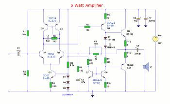
The diagram illustrates a 5W audio amplifier circuit constructed using power transistors BD139 and BD140 for the final amplification stage. This compact amplifier serves as a general-purpose amplifier suitable for applications such as computer audio, radio, MP3 players, and...