
Application of the constant current source circuit by the W7805

The W7805 voltage regulator is a linear regulator designed to provide a stable output voltage from a higher input voltage. It is typically used in applications requiring a regulated power supply. In this circuit configuration, the W7805 is utilized to establish a constant current source, which is beneficial in various applications such as LED driving, battery charging, and sensor power supplies.
In the circuit, a resistor (R) is connected between the output terminal of the W7805 and the common terminal (ground). This resistor plays a critical role in determining the output current flowing through the load (RL). The relationship between the resistor value and the output current can be expressed with the following formula:
\[ I_{out} = \frac{V_{out}}{R} \]
Where:
- \( I_{out} \) is the output current,
- \( V_{out} \) is the output voltage of the W7805, typically 5V,
- \( R \) is the resistance value in ohms.
It is essential to select the resistor value carefully to ensure that the output current remains within the safe operating limits of the W7805. The maximum output current for the W7805 is specified in its datasheet, and exceeding this limit could result in damage to the regulator.
The efficiency of the circuit can be improved by selecting a lower output voltage, as this reduces the voltage drop across the regulator, thereby minimizing power dissipation. This is particularly important in battery-powered applications where power conservation is critical.
Overall, the integration of the W7805 as a constant current source in this circuit demonstrates its versatility and effectiveness in providing reliable power to various electronic loads while maintaining efficiency and stability. Circuit as shown with W7805 positive current source application integration circuit composed of the regulator. CKS integrated voltage regulator circuit illustrated W7805 work i n suspension. After between its output terminal and the common terminal a resistor, a constant current is formed, so that the current flowing through the load RL, and then back to the power supply. Select W7805 regulator output voltage is low, mainly to improve efficiency. Adjust the size of R, it can change the value of a constant current source (of course, the regulator can not exceed the maximum output current).
Output current corresponding to the formula:
Related Circuits
The voltage to be sampled is applied to the input of R2, a 100K linear taper potentiometer, while the other end of R2 is grounded. Consequently, the signal level that is sent to the buffering level shifter U1-A and...
Figure (a) illustrates a general inverting amplifier circuit, which includes a 100k potentiometer as a feedback resistor connected in series between the input terminal and the inverting input to compensate for the DC bias current. The potentiometer (Rp) should...
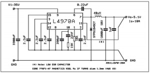
A small-sized and easy-to-build 5V 10A power supply circuit is being sought. This circuit utilizes the L4970A integrated circuit as a 10A switching regulator. It is essential that the power supply input can handle a current of 10A to...
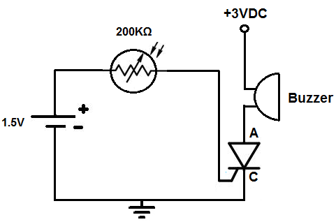
This circuit activates an alarm when it detects a specific level of light. When the light exposure increases beyond a predetermined threshold, a loud buzzer sounds, providing an alert. The alarm remains inactive in low-light conditions but triggers in...
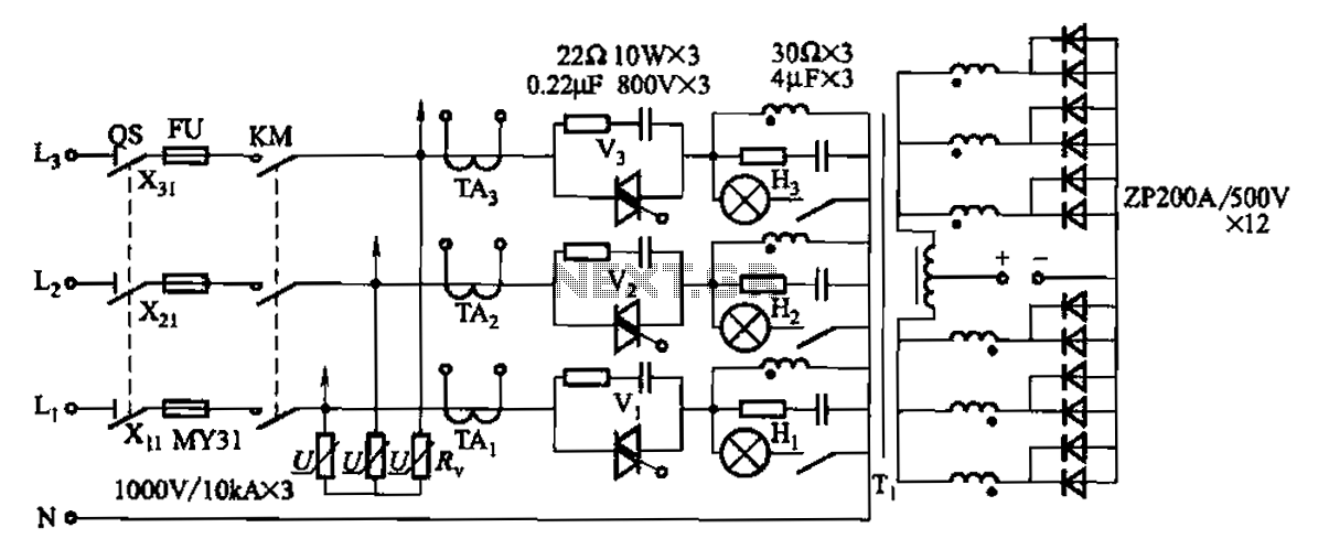
A 1500A-7V phase thyristor power regulator circuit is designed for plating applications. It consists of three major components: the main circuit, the control circuit, and the protection circuit. The control circuit includes a trigger circuit, a synchronous power supply,...
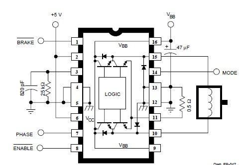
This simple DC servo motor circuit design can be utilized in various electronic projects. The circuit schematic illustrates that this DC servo motor driver employs a single integrated circuit along with a few external electronic components. For bidirectional DC...