
cut off low circuit diagram

The solid-state charge detector circuit is designed to sense minute electric fields and provide a visual indication of their presence through an LED. The core components of the circuit include a 6-volt battery, which serves as the power supply, ensuring that the circuit operates efficiently. The light-emitting diode (LED) acts as an output indicator, illuminating when a detectable electric field is present.
The field-effect IC, specifically the ADM666A, plays a critical role in the circuit's operation. This integrated circuit is known for its high sensitivity and low power consumption, making it ideal for detecting weak electric fields. The IC operates by amplifying the small voltage changes caused by the electric fields, enabling the LED to light up even when the detected signal is significantly low.
To construct the circuit, the 6-volt battery is connected to the power input of the ADM666A, ensuring that the IC receives the necessary voltage for operation. The output pin of the ADM666A is connected to the anode of the LED, while the cathode of the LED is connected to ground. A current-limiting resistor is typically included in series with the LED to prevent excessive current flow, which could damage the LED.
In summary, this solid-state charge detector circuit effectively utilizes a combination of a 6-volt battery, an LED, and the ADM666A IC to detect weak electric fields and provide a visual output, making it a valuable tool for applications requiring sensitivity to low-level electric signals.This is a circuit diagram for a solid state charge detector. It can detect very weak electric fields. The circuit has three components: a 6-volt battery, a light-emitting diode (LED), and a field-effect IC ADM666A 🔗 External reference
Related Circuits

The circuit illustrated in Figure 3-123 operates as follows: When the stop button SBz is pressed, contact KMi releases, cutting off power to the motor. Simultaneously, KMz is activated, engaging the electromagnetic brake YB to hold the motor in...

The high-temperature alarm will emit a beep and the LED will blink when the temperature of the device rises abnormally. This simple overheating alarm is designed to monitor heat levels. The high-temperature alarm circuit is an essential safety device used...

This design circuit features a simple, cost-effective amplitude-stabilized phase-shift sine wave oscillator that requires one integrated circuit (IC) package, three transistors, and operates from a single power supply. The circuit incorporates an RC network configured for phase shift, oscillating...

R1 is a 15k ohm resistor. An NTC thermistor rated at 10k ohm, available at Radio Shack in the United States, is utilized. P1 is a 10k ohm potentiometer that sets the low speed (voltage) of the fans at...
A few months ago, a first amplifier project was completed. It served primarily as a test rather than a listening device. The design utilized 9240/240 Mosfets. Future plans for enhancement or modification are being considered. The amplifier design utilizing 9240/240...
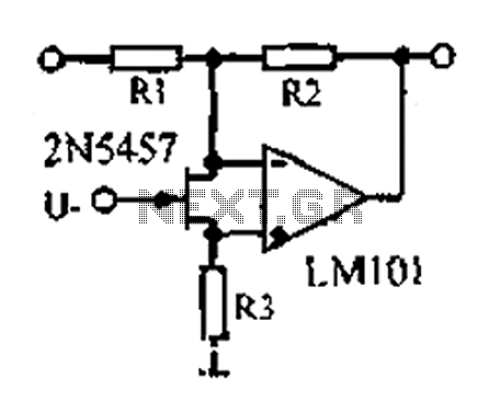
A 1.53 voltage-controlled gain amplifier (VGA) utilizes a FET connected between the two inputs of the operational amplifier (op-amp) as a voltage-controlled resistance. The resistance changes linearly with voltage and varies from several dozen square ohms, exhibiting excellent control...