
A 30 Mtr Direct Conversion Receiver for QRSS
The crystal bandpass filter/amplifier board is designed to optimize signal processing in QRSS applications. The enclosure dimensions (75 x 75 x 50 mm) are strategically chosen to minimize external interference, ensuring that the filter operates with maximum efficiency. The RF amplifier included in the module compensates for the inherent losses in the crystal filter, maintaining signal integrity throughout the processing chain.
The connection scheme utilizes standard phono sockets for seamless integration with the QRSS DC receiver. The RF output is directly linked to the receiver's antenna input, facilitating the reception of weak signals while maintaining a low current draw of approximately 35 mA at 12.5 Volts, which is efficient for portable or battery-operated applications.
The introduction of the AF Buffer Amplifier/AF Filter is a critical enhancement, particularly in environments with high levels of QRM. By preventing unwanted signals from affecting the AGC in the software, the system can maintain sensitivity to desired signals. The choice of an audio bandpass filter over a low-pass filter reflects a careful consideration of the trade-offs between complexity and performance, yielding a more robust solution to filter out noise while allowing the desired signal bandwidth to pass.
The filter's design allows for fine-tuning, which is essential for adapting the system to various operational conditions. The ability to adjust the resistors for stagger tuning provides flexibility in achieving the desired bandwidth and filter characteristics, catering to different user needs and signal environments. A "Q" value of 8 is optimal for this application, balancing filter sharpness and stability without introducing excessive ringing, which could distort the signal.
In conclusion, the crystal bandpass filter/amplifier board and its associated AF Buffer Amplifier/AF Filter represent a well-engineered solution for QRSS signal reception, combining effective filtering, amplification, and user-adjustable features to enhance overall performance in a variety of operational scenarios.The schematic for the crystal bandpass filter/amplifier board appears below (left) withimages of the assembled and boxed unit appearing below center andright. The signal frequency bandpass filter isconstructed over a ground plane and housed in its own enclosure measuring 75 x 75 x 50 mm.
The separate enclosure ensures freedom from unwanted signal "leakage" around the filter. The crystal bandpass filter module also includes a small R. F. amplifier of modest gain to compensate for the small loss in the crystal filter. The module is fitted with phono sockets for Antenna I/P and R. F. O/P. The R. F. O/P of the filter/amplifier module is connected to the antenna I/P of the QRSS DC receiver. The current drawn by this module is about 35 mA @ 12. 5 Volts which includes the L. E. D. `s. The direct conversion receiver and filter/amplifier modules together provide a very effective QRSS receiver, a further improvement can be made with the addition of the A. F. Buffer Amplifier/A. F. Filter described below. Note: (Added 25/10/06) The unit about to be described was added to the DC-RX in an attempt to further improve the performance though I have to admit the improvement was hardly noticeable except under conditions of heavy QRM when signals close to the QRSS sub band would confuse or desensitize Argo.
Since this unit was built I have had some time to evaluate it more fully and would suggest that usingop-amps with a lower noise figurewould give improved performance. My feeling is that the A. F. filter is a worth while optional extra for those times when QRM is a problem. The A. F. Buffer Amplifier/A. F. Filter module was added to the receiver to ensure that the software A. G. C. in Argo was not "confused" by unwanted signals which appear in the audio passband of the DC-RX. These signals arise from other users of the 30 Mtr band (CW, RTTY etc) which are within the bandpass of both the front end (RF) filter and the audio stages of the receiver.
These unwanted signals can cause "desensitization" of Argo such that wanted signals appear weaker than they actually are. Initially a low pass audio filter was considered but it was soon realized that with little or no additional complexity an audio bandpass filter could be used which would offer better performance.
The low frequency roll-off of the bandpass A. F. filter helps to reduce any possible power line noise from reaching the P. C. sound-card and also offers attenuation of unwanted signals below the 100 Hz window used for QRSS. It was also felt that the original DC RX design was perhaps lacking in AF gain. To much gain risks overloading the sound-card on strong signals but my feeling was that a little more audio gain could be tolerated. I came to this conclusion for two reasons, the atmospheric noise was barely audible which made me wonder if I was achieving optimum sensitivity and secondly the additional gain from another low noise amplifier stage would lift the wanted signal level far above the noise level which may result from the Op-Amp`s used in the active bandpass filter.
A full schematic for the A. F. Buffer Amplifier/A. F. Filter is shown below. The center frequency of the A. F. Filter was chosen to match the center of the QRSS sub-band as it appears in Argo. This frequency may not be the same on your DC RX and may require adjustment to suit the frequency of the crystal you use. For use with Argo frequencies between 1 and 2 kHz should be suitable. Fine tuning of the A. F. filter can be performed by adjustment of the two resistors (Rx2 and Rx3 in the circuit diagram), adjusting these resistors individually can also permit "stagger" tuning of the two cascaded filter stages.
This can be useful if a wider B. W. is required. In my version of the filter I found a "Q" of 8 to be more than enough with higher "Q" values causing excessive "ringing" of the filter. Note: With the component values shown in the schematic the filter may ap 🔗 External reference
Related Circuits
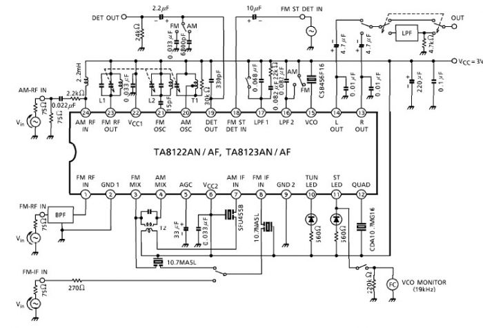
A simple low-power AM/FM radio receiver electronic project can be designed using the TA8122 integrated AM/FM receiver, manufactured by Toshiba Semiconductor. This radio receiver circuit is suitable for portable radio applications or other similar devices. The TA8122 radio receiver...
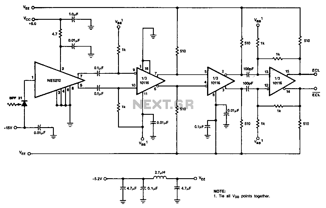
This receiver utilizes the NE5212, the Signetics 10116 ECL line receiver, and the Phillips/Amperex BPF31 pin diode. The circuit is a capacitor-coupled receiver that employs positive feedback in the final stage to introduce hysteresis. The level of hysteresis can...
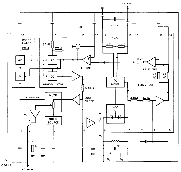
GENERAL DESCRIPTION The TDA7000 is a monolithic integrated circuit designed for mono FM portable radios or receivers, emphasizing minimal peripheral components to achieve compact dimensions and reduced costs. This integrated circuit features a Frequency-Locked-Loop (FLL) system with an intermediate...
Flying hand launch gliders necessitate the use of small-capacity receiver NiCad battery packs. While these lightweight packs are advantageous, they have the significant drawback of quickly depleting. Although careful timing of flights can be employed, it often results in...
The Command radio refers to the radio function used for communication between aircraft rather than a specific model. The "Command" function facilitated communication within the aircraft, while the "Liaison" function was intended for communication back to base. The distinctions...
This document describes a simple 2.4 GHz SWR meter that utilizes surplus microwave hardware. The main component is a MECA -20/-20 dB Directional Coupler, which operates within a frequency range of approximately 700 MHz to 2.5 GHz. This directional...
Warning: include(partials/cookie-banner.php): Failed to open stream: Permission denied in /var/www/html/nextgr/view-circuit.php on line 713
Warning: include(): Failed opening 'partials/cookie-banner.php' for inclusion (include_path='.:/usr/share/php') in /var/www/html/nextgr/view-circuit.php on line 713