
Precision Receiver Battery Low Voltage Alarms

The circuit described integrates several essential components that work together to monitor battery voltage levels effectively. The LM336 voltage reference ensures a stable 2.5V output, which is crucial for accurate voltage comparisons. The LM311 comparator's role is vital, as it continuously monitors the sampled voltage against the reference voltage, providing timely alerts to the user. The use of a voltage divider allows for flexibility in setting the alarm threshold, accommodating various battery capacities and user preferences.
The addition of a capacitor, although not part of the initial design, can significantly enhance the circuit's performance by filtering out transient voltage spikes caused by servo operation. This smoothing effect minimizes false alarms, allowing for a more reliable indication of the battery's state. The design's lightweight and compact nature makes it suitable for applications where weight is a critical factor, such as in hand launch gliders.
For optimal performance, it is recommended to conduct initial tests with the specific battery and servo configuration to calibrate the system accurately. Adjusting the resistor values in the voltage divider can tailor the alarm settings to meet the user's requirements, ensuring that the system provides adequate warnings before battery depletion occurs. This proactive approach to battery management enhances the reliability and safety of flying hand launch gliders, allowing for more enjoyable and less stressful flying experiences.Flying hand launch gliders means living with small capacity receiver NiCad battery packs. These small packs are light, but have the distinct disadvantage of rapidly depleting. You can carefully time your flights, but you end up either crashing when your plane seizes or using only a portion of the already small capacity of the battery. If you charg e the battery in a slightly suboptimal fashion, your plane dies and bites the dirt (done that, crashed). This devices will allow you to use a small mA pack and use the full capacity of your battery. This device of my design uses seven componants on a single side PC board. With a 6 inch connector, the whole thing weighs about 0. 2 oz. The alarm sounds with a voltage at or below 4. 5v, and the circuit draws 2. 4-2. 7 mA when quiet and 5. 6mA with the alarm (in my Hitec system, a receiver and two servos draw an average 75-100mA when flying).
The LM336 and 3k resistor provide a precision reference 2. 5 volts, and the two other resistors are a voltage divider that provide the sample voltage. The LM311 is a voltage comparator, and powers the buzzer when the sample voltage crosses the reference. Since servos draw current abruptly and intermittantly, the ambient battery voltage is puncuated by a series of low voltage spikes.
The capacitor (not in the original design in the picture) smooths these spikes somewhat so that the alarm does not chirp with every servo motion. These inverted voltage spikes are not so pronounced with larger capacity batteries; the capacitor may not always be be needed.
While it is possible to smooth the voltage completely, this chirping provides a continuous and early indication of battery voltage. With the circuit here, the alarm chirps while slewing both servos of a reciever/two servo system when a 150mA battery is about half discharged, chirps with any servo motion when near completely discharged, and alarms continuously with about 5 minutes of flying time left.
With a larger capacity battery, the sequence occurrs much nearer to complete discharge-perhaps no capacitor or a smaller one (say 1uf or 0. 1uf) would do-and initial comparison with your measured voltages would be important to calibrate to your system.
You can adjust the divider resistors for a higher or lower voltage alarm: Vout=Vin(R2/(R1+R2) where Vout=2. 5v and Vin is your selected alarm voltage, and R1 is the positive side and R2 is the negative side. Note that the LM336 has three pins and you only use two (break off the third). Solder a battery or servo connector to the board with positive and negative as shown, and plug the connector into an unused slot in your receiver.
🔗 External reference
Related Circuits
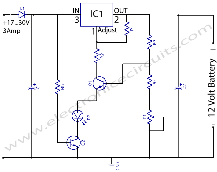
12 Volts Lead Acid Battery Charger Circuit. Apart from serving as a standard battery charger, this circuit is ideal for providing a constant charge to a 12-Volt lead-acid battery. This 12-Volt lead-acid battery charger circuit is designed to efficiently charge...
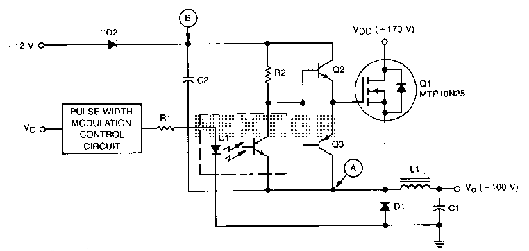
This circuit is essentially a classic buck regulator that utilizes a TMOS N-channel power FET for the chopper and generates its own supply for gate control. The unique feature of this circuit is its method for creating a separate...
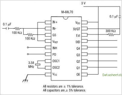
The MAX2385 and MAX2386 LNA mixer integrated circuits (ICs) are designed for CDMA, cdma2000 1x, and GPS applications. These ICs are optimized for the Japanese frequency band of 832 MHz to 870 MHz and can also be configured for...
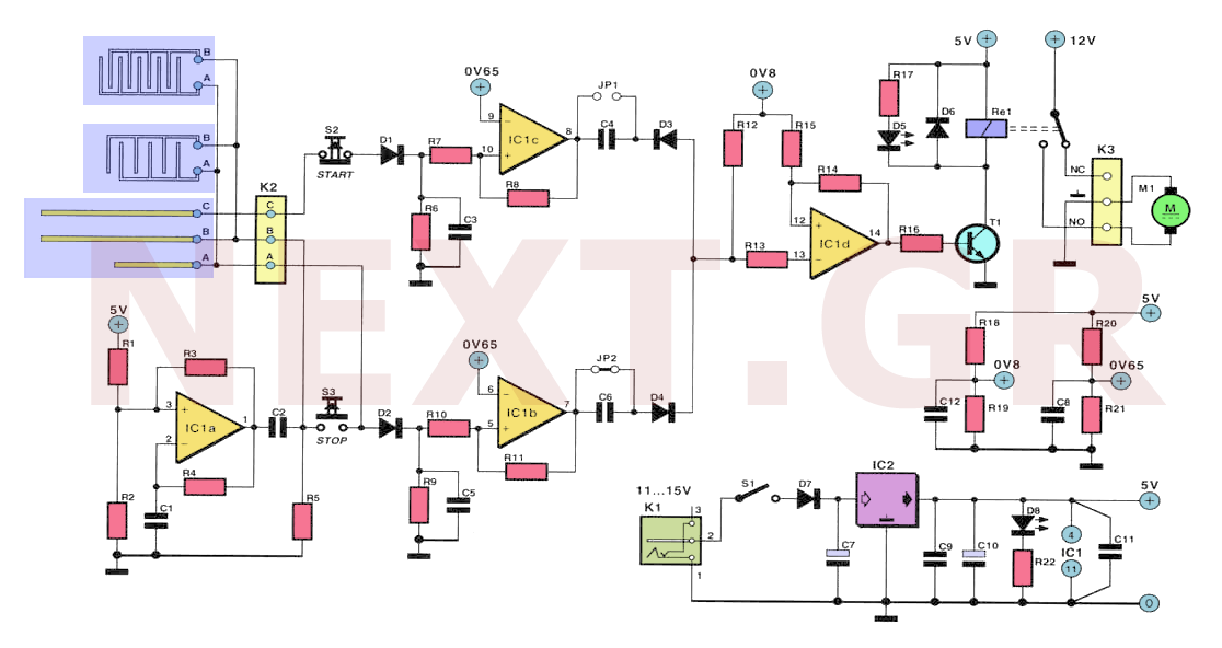
Often, for various reasons, individuals forget or are unable to water the plants in their homes. Many humidity sensor units merely alert users with a beeping sound or a flashing light when the pot requires watering. However, what if...
The 555 oscillator operates with a +12V supply and ground, without the need for a -12V supply. The 555 timer IC is a versatile component commonly used in various oscillator and timer applications. In this configuration, the circuit is powered...
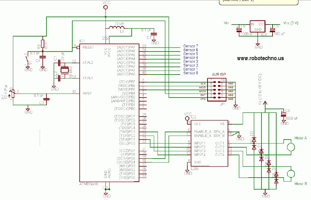
This line follower robot utilizes the following components: eight phototransistor proximity sensors, an ATMega16 microcontroller, an L298 motor driver, and is programmed using the C programming language. The line follower robot is designed to navigate along a designated path by...