
Digital Clock Circuit-CMOS 4047

The circuit design utilizes the CMOS 4047, which is a versatile device capable of operating in both monostable and astable modes. In astable mode, the 4047 produces a continuous square wave output, the frequency and duty cycle of which can be adjusted through external resistors and capacitors connected to its timing pins. This square wave output is characterized by its clean transitions and low power consumption, making it suitable for driving digital logic circuits.
In the context of driving 4-bit binary counters, the square wave output from the 4047 can be connected to the clock input of a CMOS decade counter, such as the 4017 or 4026 series. This configuration allows for counting sequences in binary, where each pulse from the 4047 increments the counter by one. The output of the counter can then be used to drive LEDs or other display devices, providing a visual representation of the counting process.
The circuit can be further enhanced by incorporating additional components, such as diodes for signal conditioning or transistors for buffering the output if higher current drive capabilities are required. Proper power supply decoupling should also be considered to ensure stable operation of the CMOS devices involved. Overall, the combination of the CMOS 4047 and a 4-bit binary counter creates a robust and efficient digital counting circuit suitable for various applications in digital electronics.This circuit provides a digital square wave that can be viewed directly or used to drive other circuits. It used the CMOS 4047 Low-Power Monostable/Astable Multivibrator. As used in Tom Duncan`s Adventures with Digital Electronic`s Book, to drive CMOS Decade of 4-bit binary counters.
🔗 External reference
Related Circuits
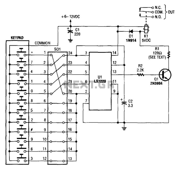
A keypad is used to input a four-digit access code, which is configured using jumpers on a 24-pin plug-in header and socket. The component Ul is an LST220, which detects a sequential four-digit data input. Upon successful entry of...
This electronic clock comprises the LM8365 and the LDD640R displays. The LM8365 can show the hour/minute and month/day. Users can set two alarm outputs, AD1 and AD2, by pressing either the 12h or 24h button. The operating voltage range...
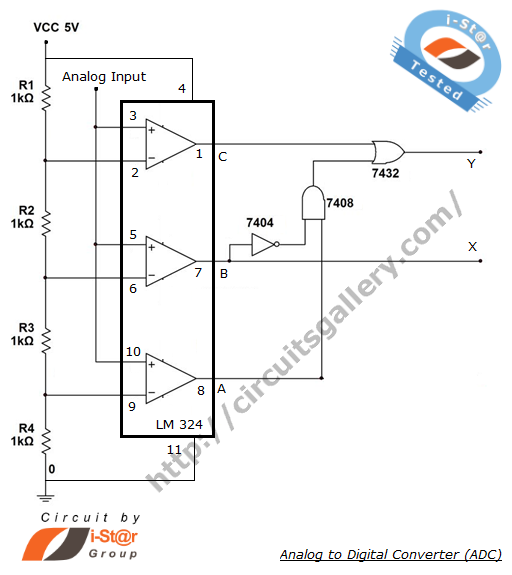
The process of converting an analog voltage into an equivalent digital signal is known as Analog to Digital Conversion (ADC). An ADC is an electronic circuit that converts its analog input to a corresponding binary value. The output depends...
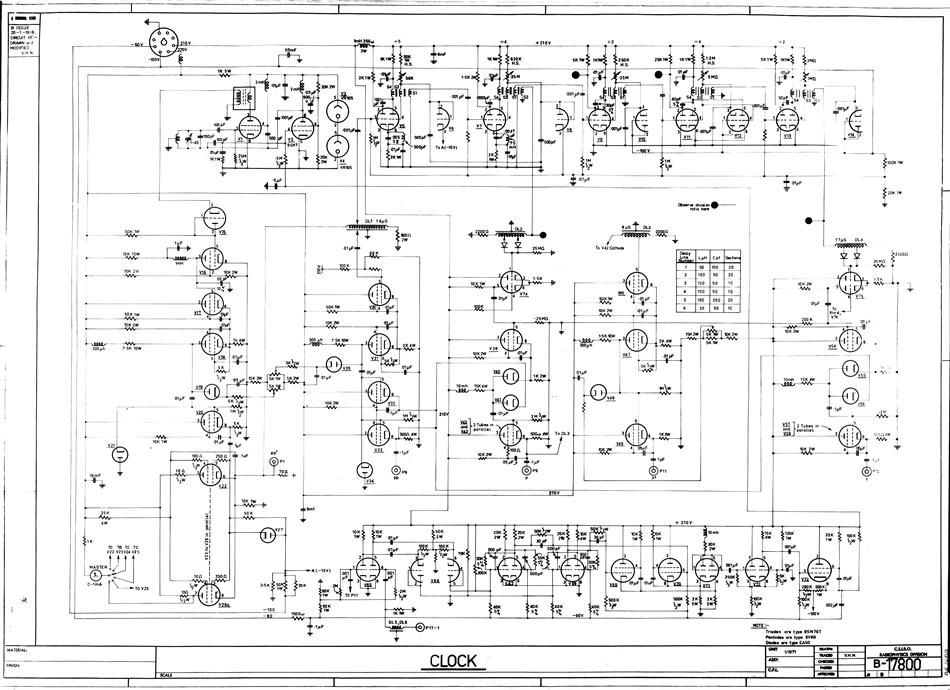
A hard copy schematic diagram related to the computer CSIRAC. The schematic diagram illustrates the detailed connections between all components in the circuit. It is used for building the circuit and later for testing. For CSIRAC, the most common...
The I2C serial bus is a widely used two-wire bus for small-area networks. The I2C Clock and Data lines feature open collector (or drain) outputs for each device on the network, requiring only a single pull-up resistor. This architecture...
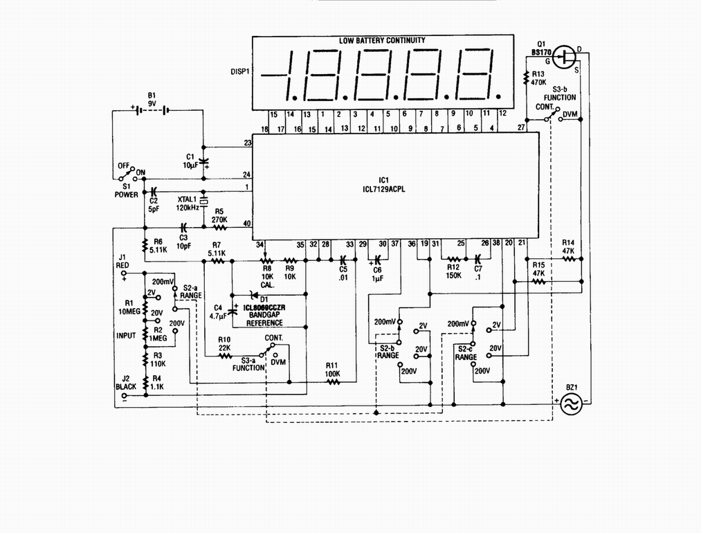
Single-chip digital voltmeter. This 4 1/2-digit DVM circuit is built around a Maxim ICL7129ACPL A/D converter and LCD driver. An ICL8069 CCZR 1.2-V band-gap reference diode is used for accuracy. The described circuit is a single-chip digital voltmeter (DVM) utilizing...