
A 4 Watt Amplifier Portable RadioCircuit Design using TDA1011

The 4 Watt Amplifier Circuit is designed to provide audio amplification in portable radio devices, ensuring sufficient power output for driving small speakers. The TDA1011 is a high-performance audio amplifier IC that offers low distortion and high efficiency, making it suitable for battery-operated applications.
The circuit typically includes the following components: the TDA1011 IC, resistors, capacitors, and a power supply. The input signal is fed into the amplifier through the input capacitor, which blocks any DC component while allowing the AC audio signal to pass. The gain of the amplifier can be set using external resistors connected to the feedback loop, allowing for customization based on the application requirements.
Power supply considerations are crucial; the TDA1011 operates efficiently within a specified voltage range, typically between 9V to 15V. Bypass capacitors are used near the power supply pins of the IC to filter out any noise and ensure stable operation.
The output stage of the amplifier is designed to drive a speaker directly, often with a series output capacitor to block DC voltage from reaching the speaker. This configuration helps to protect the speaker and improve sound quality.
Thermal management is also an essential aspect, as the amplifier can generate heat during operation. Adequate heat sinking or thermal pads may be necessary to dissipate heat and maintain optimal performance.
Overall, this amplifier circuit is ideal for portable radio applications, providing an effective solution for audio amplification while maintaining low power consumption and high sound quality.The following schematic depicts the design of a 4 Watt Amplifier Circuit Diagram for portable radio application using TDA1011 from Philips Semiconductor. The.. 🔗 External reference
Related Circuits
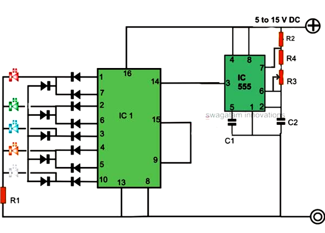
An LED light chaser circuit is an electronic configuration designed to illuminate a group of LEDs in a predetermined sequence. A commonly used integrated circuit (IC) for creating this type of LED sequencer circuit is the 4017. This IC...
This circuit differs from similar circuits in view of its simplicity and a totally different concept of generating the control signals. Usually remote control circuits make use of infrared light to transmit control signals. Their use is thus limited...
The Cymbal monoblock power amplifier features a modern push-pull design utilizing ultra-linear 6H30 triodes in a zero-feedback circuit. This unique configuration is optimized for sound quality rather than sheer power, making it ideal for efficient drivers and horn speakers....
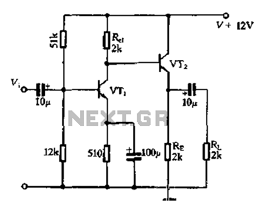
Available RC coupling between its two stages can also be directly coupled. This is in addition to the common-emitter total radio circuit configuration, which is widely used. Outside the previously described common-emitter circuit, a total group or common-emitter circuit...
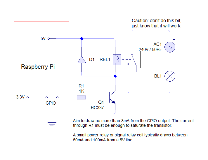
The circuit requires only four components, with a total cost of approximately 70 pence, making it an ideal candidate for classroom exercises. A low-cost relay, such as the Omron G5LA-1 5DC, can switch loads up to 10A at 240V....
The preamplifier that appears in the figure is a completely symmetrical preamplifier, from the input as the exit and it works in Class A. It does not have somebody innovation, simply it uses good solutions, in order the result...