
Raspberry Pi Driving a Relay using GPIO

The circuit comprises four components: a relay with a 5V DC coil, a BC337 NPN transistor, a diode, and a 1K resistor. The transistor energizes the relay's coil with the necessary voltage and current. Relays typically have three key voltage/current ratings: coil, AC load, and DC load. The coil rating indicates the required current at a specified voltage to activate the switch, sometimes expressed in milliwatts (mW). The AC and DC load ratings refer to the switch contacts and specify the maximum load current that can be handled at the given AC and DC voltages. DC loads are rated lower due to increased arcing, which can lead to contact wear and eventual failure. Generally, larger loads necessitate heavier contacts, which require larger coils and more power from the circuit.
Relays may not fit easily onto a breadboard, so constructing the circuit on veroboard is advisable. Alternatively, the relay can be mounted on veroboard with two pins added for the coil contacts, allowing for breadboard connections. It is imperative to avoid connecting AC mains to a breadboard.
In the example code, GPIO pin 17 is utilized, which corresponds to pin 11 on the Raspberry Pi's 26-pin expansion header. This pin is located opposite GPIO pin 18 (PCM_CLK) and next to GPIO pin 21 (PCM_DOUT). The selection of GPIO 17 was made to minimize potential conflicts with other peripherals. Although marked as 3.3V on the schematic, this should not be confused with the 3V3 pin; the labeling indicates that a 3.3V GPIO pin is capable of driving a 5V load, and it could also drive a 24V coil if supplied by an appropriate DC power source instead of the Raspberry Pi's 5V line.
To activate the relay, the circuit sends a few milliamps at 3.3V from the GPIO pin through a 1K resistor (which may be increased to 1.2K to limit the current to below 3mA). This current is sufficient to saturate the BC337 transistor, allowing current to flow through the 5V rail and the relay's coil. Various general-purpose NPN transistors with a minimum hFE of 50 to 100 can be used in place of the BC337, depending on the current drawn from the GPIO pin, the current required to energize the relay's coil, and the actual hFE of the transistor in use, as these can vary significantly.
The diode in the circuit serves to conduct the current generated by the de-energizing coil back across the transistor, protecting the circuit from voltage spikes that could occur when the relay is switched off. This configuration ensures safe and reliable operation, making it suitable for educational purposes and practical applications.There are only four components required, and the cost for these is around 70p, so it would be a good candidate for a classroom exercise. Even a cheap relay like the Omron G5LA-1 5DC can switch loads of 10A at 240V. A word of caution: don`t tinker with mains voltages unless you`re really (really) sure about what you`re doing.
A mechanical relay allows a safe learning environment, since you can switch any load with it (e. g. a 9V DC battery/bulb circuit for testing), and the concept of a mechanical switch is very easy to grasp. A more efficient alternative to switch an AC load would be to use a solid-state relay (e. g. opto-coupled Triac), but it`s quite easy to make a wrong assumption and blow everything up with a loud bang and a big spark.
I recommend sticking with mechanical relays until you`re entirely sure about what you`re doing. Tip: you can buy plug-in low-voltage AC power-supplies if you want to play with triacs. There are four components to this circuit. A relay (5V DC coil), a BC337 NPN transistor, a diode, and 1K resistor. Essentially, the transistor is used to energise the relay`s coil with the required voltage and current. A relay will often have 3 significant voltage/current ratings specified; coil, AC load, and DC load. The most important to our circuit is the coil rating, which is the current at a specified voltage required to energise the coil (activate the switch), sometimes expressed as milliwatts (mW).
The AC and DC load ratings relate to the switch-contacts, and state the maximum load current (e. g. for your lamp, motor, etc. ) that can be carried at the given AC and DC voltages. DC loads are rated lower because they arc (spark) more, which eventually wears the contacts to the point of failure. In general, large loads need heavier contacts, which in turn need bigger coils to switch them, and bigger coils need more power from your circuit.
Relays sometimes don`t fit easily onto a breadboard, so you might want to build the circuit on veroboard instead, or just mount the relay on veroboard and add two pins for the coil contacts (allowing you to breadboard it). Don`t ever put AC mains into your breadboard! The GPIO pin used in the example code is GPIO_17, which appears on pin 11 of the Raspberry Pi`s 26-pin expansion header (opposite GPIO_18 (PCM_CLK) and beside GPIO_21 (PCM_DOUT).
The choice of GPIO 17 was simply because I considered it less likely to conflict with other peripherals likely to be in use. Although the pin is marked 3. 3V on the schematic, don`t confuse this with the 3V3 pin I labelled it with the voltage to highlight that a 3.
3V GPIO pin is driving a 5V load it could also drive a 24V coil, for example, if an appropriate DC power supply is used rather than the Raspi`s 5V line. Essentially, to activate the relay, all the circuit does is send a few milliamps at 3. 3V from the GPIO pin, through a 1K resistor (you may choose to increase this to 1. 2K if you want to be strictly below 3mA). This current is enough to saturate the BC337 transistor, causing current to flow on the 5V rail through the transistor, and therefore also through the relay`s coil.
Most general purpose NPN transistors with an minimum hFE of say 50 to 100 could be used in place of the BC337 it will depend on a) how much current you`re willing to draw from the GPIO pin, b) how much current is required to energise the relay`s coil, c) the actual hFE of the transistor in your hand, since they vary wildly and the current gain could easily be significantly more than the stated minimum. The diode in the circuit is there to conduct the current generated by the de-energising coil back acro
🔗 External reference
Related Circuits
This circuit is a simple analog multiplier. The operation of the circuit can be understood by considering A2 as a controlled gain amplifier that amplifies V2, with its gain dependent on the ratio of the resistance of PC2 to...
The PR4403 is an advanced version of the PR4402 40mA LED driver. It features an additional input known as LS, which can be activated by pulling it low to illuminate the LED. This functionality simplifies the construction of an...
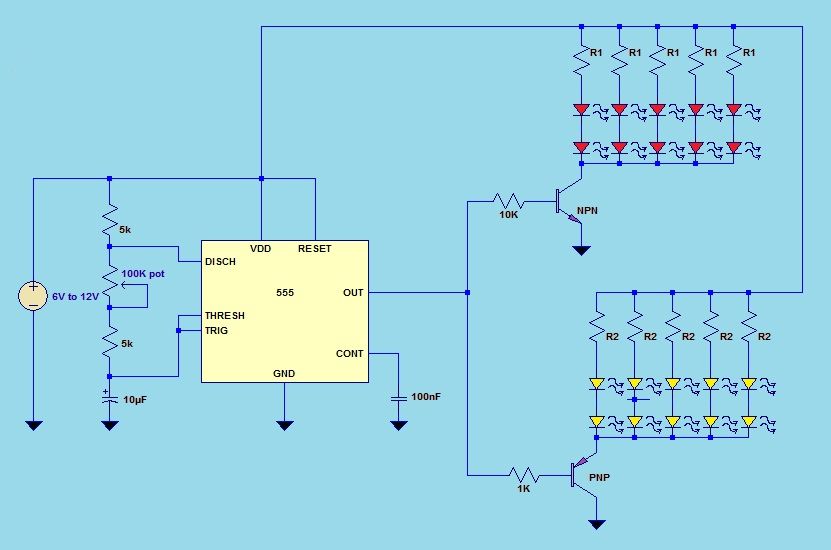
This project utilizes a 555 timer integrated circuit (IC) in an 8-pin configuration to control multiple LEDs. It is designed for quick assembly and allows for the adjustment of timing functions. The circuit employs a 555 timer in astable mode,...
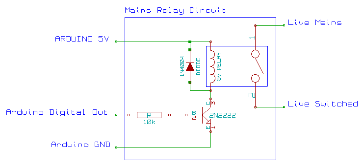
This mains AC relay module utilizes 5V relays that can be powered directly from an Arduino and can switch 230V. A basic energy monitoring and control system has been constructed using an Arduino 2009, off-the-shelf wireless remote control sockets,...
Create a USB to Serial Converter using the ATmega8 microcontroller. The firmware source code for the ATmega8 is available for free download. Since the ATmega8 does not natively support USB communication, the USB communication protocol must be implemented within...

This application note discusses the use of SEPIC power modules to supply the necessary power for driving high-brightness LED arrays. These arrays serve as display backlights and necessitate a wide dimming range. The SEPIC configuration offers an efficient and...