
A Bedside Lamp Timer Circuit Schematic

This circuit utilizes a simple yet effective design to manage the operation of a lamp, incorporating user-friendly features for convenience. The primary components include two integrated circuits, a relay, resistors, and capacitors, which work together to create a timed switch. The use of transistors Q1 and Q2 ensures low power consumption when the circuit is inactive, which is crucial for energy efficiency.
The pushbutton P1 acts as the primary control for initiating the circuit, while P2 provides an immediate off function, allowing users to control the lamp without needing to wait for the timer to expire. The LED indicator serves a dual purpose by providing visual feedback when the lamp is in operation and signaling the impending shut-off through its blinking pattern.
The timing mechanism relies on the RC timing circuit formed by R4 and C4, which determines the duration of the lamp's operation and the blinking intervals. Adjusting these components allows for customization of the timing to suit different user preferences. Additionally, the option to include a piezo sounder adds an auditory signal to the visual feedback, further enhancing user awareness of the lamp's status.
Overall, this circuit exemplifies a practical application of basic electronic components to create a useful device for everyday scenarios, particularly in settings where automated control of lighting is beneficial.The purpose of this circuit is to power a lamp or other appliance for a given time (30 minutes in this case), and then to turn it off. It is useful when reading at bed by night, turning off the bedside lamp automatically in case the reader falls asleep.
After turn-on by P1 pushbutton, the LED illuminates for around 25 minutes, but then it starts t o blink for two minutes, stops blinking for two minutes and blinks for another two just before switching the lamp off, thus signaling that the on-time is ending. If the user want to prolong the reading, he/she can earn another half-hour of light by pushing on P1.
Turning-off the lamp at user`s ease is obtained by pushing on P2. Q1 and Q2 form an ALL-ON ALL-OFF circuit that in the off state draws no significant current. P1 starts the circuit, the relay is turned on and the two ICs are powered. The lamp is powered by the relay switch, and IC2 is reset with a positive voltage at pin 12. IC2 starts oscillating at a frequency set by R4 and C4. With the values shown, pin 3 goes high after around 30 minutes, turning off the circuit via C3. During the c6 minutes preceding turn-off. The LED does a blinking action by connections of IC1 to pins 1, 2 & 15 of IC2. Blinking frequency is provided by IC2 oscillator at pin 9. The two gates of IC1 are wired in parallel to source more current. If required, a piezo sounder can be connected to pins 1 & 14 of IC1. Obviously, timings can be varied changing C4 and/or R4 values. 🔗 External reference
Related Circuits
This article presents basic circuits for pulsing infrared LEDs and low-power visible semiconductor lasers utilizing inexpensive and readily available components. Numerous interesting and practical applications are referenced, alongside several online resources. The focus of the article is on the...

This is a simple 555 timer circuit suitable for oscillating applications. To slow down the strobe effect, replace the 220 µF capacitors with 1000 µF capacitors. For a faster strobe effect, use a 150 µF capacitor. Additionally, R1 can...
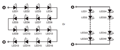
A series combination of 16 LEDs provides a luminance (lux) equivalent to a 12W bulb. However, if two series combinations of 23 LEDs are connected in parallel (totaling 46 LEDs), the output is equivalent to a 35W light bulb....
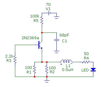
The Colpitts oscillator has been redrawn for clarity. The inductor (L) is approximately 1.5 µH with 19 turns wound on a T50-6 core (yellow). The capacitor (C6) value has been determined experimentally, with a combination of 69 pF (using...
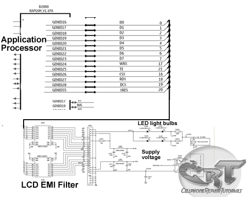
An LCD (liquid crystal display) is an electronically modulated optical device composed of multiple pixels filled with liquid crystals, arranged in front of a light source (backlight) or reflector to generate images in either color or monochrome. The block...
After turning off TT2, the input signal enters through chi Az, where the input resistance is very high and reaches the same potential. The inverting input terminal must also be associated with this movement. Therefore, Trr functions as a...