
simple 555 timer circuit

The described circuit utilizes a 555 timer IC configured in astable mode, which allows it to generate a continuous square wave output. The frequency and duty cycle of the oscillation are primarily determined by the capacitor and resistor values connected to the timer.
In this configuration, two timing capacitors (C1 and C2) are employed, where replacing the 220 µF capacitor with a 1000 µF capacitor increases the time period of the oscillation, thus slowing down the output frequency. Conversely, substituting in a 150 µF capacitor will reduce the time period, resulting in a faster oscillation frequency.
The resistor R1 plays a critical role in defining the charge and discharge times of the timing capacitor. By experimenting with different resistor values, such as 470 ohms or 910 ohms, the user can fine-tune the frequency of the output signal to meet specific application requirements.
The 555 timer circuit is widely used due to its versatility and ease of implementation in various electronic applications. It can be utilized in strobe lights, tone generators, and pulse-width modulation applications, among others. Proper selection of components allows for customization of the output characteristics, making it suitable for different tasks within electronic projects.
For optimal performance, ensure all connections are secure and components are rated appropriately for the voltage and current levels in use.This is a simple 555 circuit perfect for osculating circuits if you wont the strobe slower swap the 220uf capacitors for some 1000uf capacitors and if you wont it faster try some 150uf capacitor and you can also change out R1 to, try 470 or 910 ohms and if you have any questions ask my by leaving your questions in the comment box or email me at er icgoodchild@yahoo. com 🔗 External reference
Related Circuits
There are two independent modeling light circuits for the P2000D, one for each of the two channels. The modeling light circuit is completely separate from the high voltage strobe circuitry, even featuring its own On/Off switch. Therefore, the functionality...
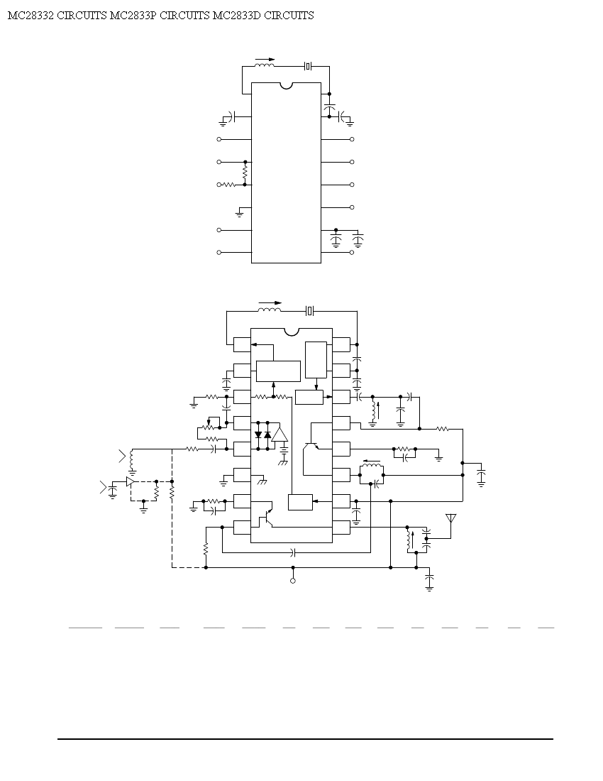
Crystal X1 operates in fundamental mode and is calibrated for parallel resonance with a load capacitance of 32 pF. The final output frequency is produced through frequency multiplication within the MC2833 integrated circuit (IC). The RF output buffer at...

The FM modulator circuit is a straightforward FM modulation design utilizing the IC 555, where the resulting modulated signal is dependent on the frequency of the input signal. The output signal is stable and of good quality, eliminating the...

Capacitor start single-phase induction motor circuit configuration, in order to form a two-phase rotating magnetic field, starting winding and capacitor in series, the same magnetic field can be formed automatically. The capacitor start single-phase induction motor utilizes a specific circuit...
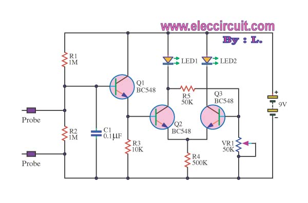
This is a false capture circuit or lie detector circuit. The basic principle is based on the resistance of human skin. While dry skin has a resistance of about 1 Megaohm. The lie detector circuit utilizes the principle of galvanic...
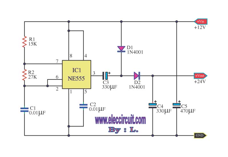
This is a simple voltage doubler circuit that converts 12V DC into 24V DC. It utilizes the popular NE555 timer IC along with a few additional components. The circuit can provide approximately 50mA of current, making it suitable for...