
A touch-AC electronic switching circuit

The circuit described operates as a touch-sensitive switch utilizing both capacitive sensing and transistor amplification. The initial touch triggers the rectification of AC voltage induced by the human body, which is then filtered to produce a usable DC voltage. The transistor amplifier (H) plays a crucial role in amplifying the input signal, allowing for reliable triggering of subsequent components.
The two paths for the electrode current serve to control the state of the transistors in a manner that is responsive to the duration of the touch. The design ensures that a brief touch does not significantly impact the capacitor's voltage, preventing unwanted triggering of the thyristor. In contrast, a prolonged touch allows for sufficient current to flow through the charging resistor (Rz), enabling the capacitor (C3) to reach the threshold voltage necessary to deactivate the transistor (n) and thus the thyristor (BCR), resulting in the light bulb (DZ) turning off.
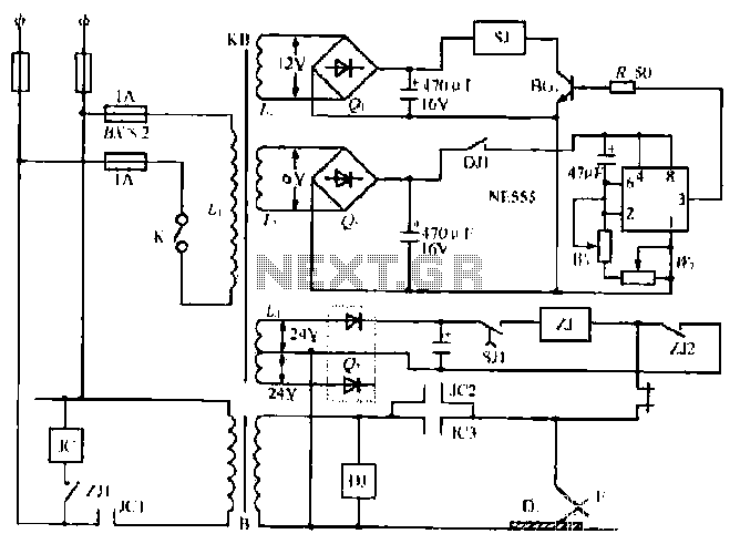
The use of a thyristor as a BCR diac in this circuit is particularly effective for controlling high-power loads, as it can handle significant currents while remaining in a stable state once triggered. The LED indicator provides visual feedback on the operational status of the circuit, enhancing user interaction. Overall, this circuit design illustrates an efficient method of interfacing human touch with electronic control systems, suitable for applications in automation and remote control.Diagram 2 shake tube n. Capacitance C. Trigger voltage rectifier filter element. H is a trigger voltage transistor amplifier circuit, three pull tube n, U, v. Composition trigg er thyristor as BCR diac. LED switching status display, c6. G. day. DW, dish for the power circuit section. When touched with a finger briefly under speculation inch touch sheet, the bodys AC induction voltage through the diode rectifier, capacitor c, filter plus obtain a pulsating DC voltage, input A transistor base so conduction, H set an electrode current two routes, all the way to the flow of R.V2 base because it is a short touch, so collector current is short, the current does not cause C, the voltage changed greatly .K not turned on, and the other JL! stream troops, R, U G pole, so n will have collector current flowing through the n base, so n.V4 from off state into saturated conduction state exhausted, the n-nest high electrode electrically him (nearly 6V supply voltage).
the a current through the SCR system very romantic person, SCR BCR conducting open shoulder .DZ light bulb. and when the high potential electrode V-ju, will maintain the current through the island, K3 inflows U base, maintain U.
the V4 saturated conduction state. to turn off power to the switch, just simply touching a finger again to bring films, Rang contact time is more than 3 seconds, so collector electrode has a longer duration of current flows through Rz charge to C3, when the white charging to 0.7V, n is turned off and the n low potential, V4 also turned off thyristor gate current losing BCR cut LL.DZ lamp goes out. after touch-up, U, V held in the off state.
Related Circuits
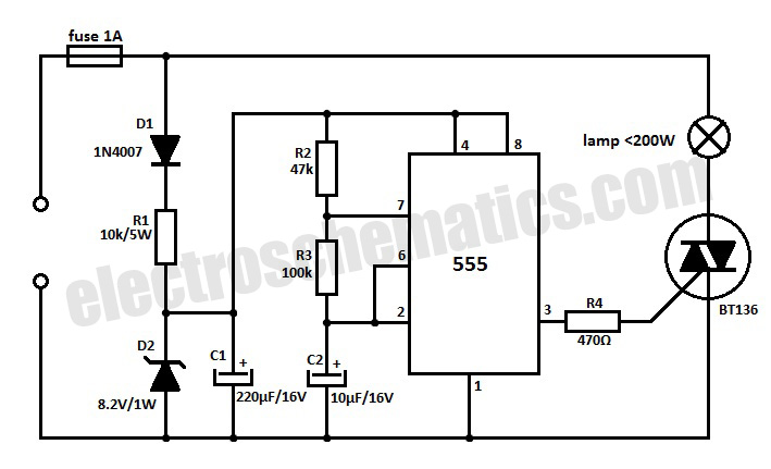
This 220V mains operated solid-state flashing lamp circuit utilizes a 555 timer integrated circuit (IC) to manage the ON and OFF durations of a triac that regulates power to the load. The circuit operates at a mains voltage of 220V,...
This circuit provides a simple visual indication of audio level signals, adaptable to various user requirements. It can be configured for different input levels, which can be adjusted using trimmer potentiometers TR1 (state) and TR2 (gain). The audio signals...
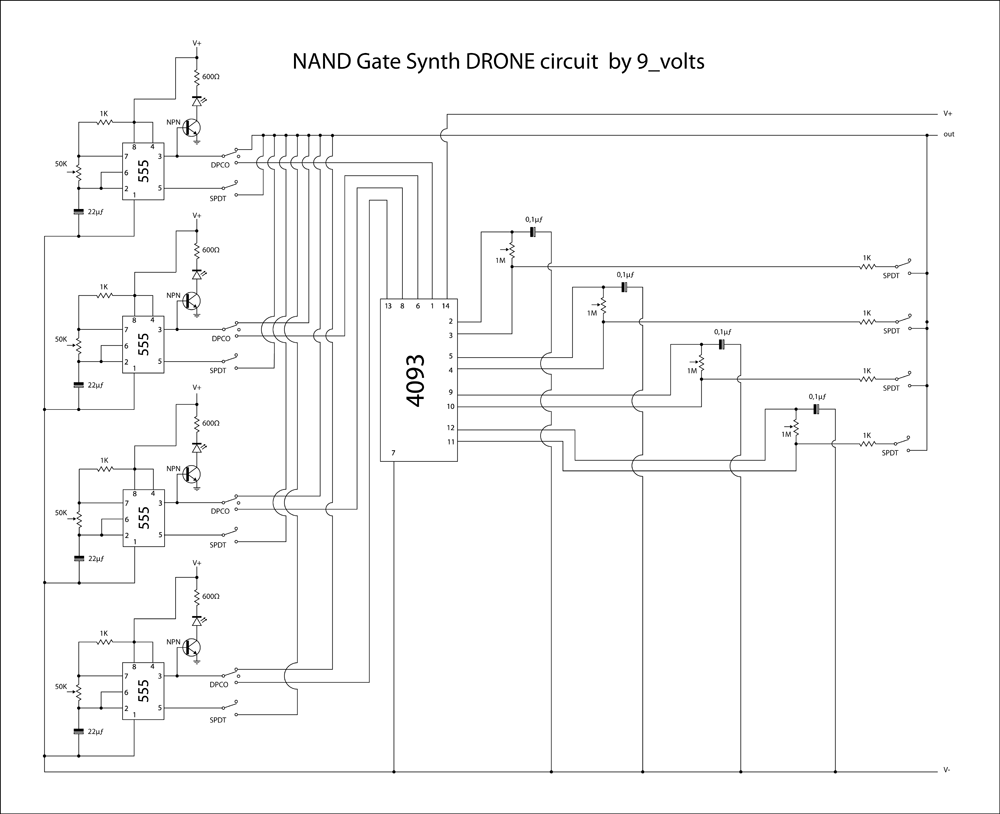
This is a brief jam session to explore the capabilities of a recently completed step sequencer. This device is quite enjoyable and expands creative possibilities. A detailed post with the circuit and instructions for building it will be provided...
The NE555 timer circuit functions as a vibration generator. The input pin 3 produces pulse frequencies ranging from 5 to 20 Hz. The circuit includes a fan that operates within a bamboo enclosure. The barrel section is designed to...
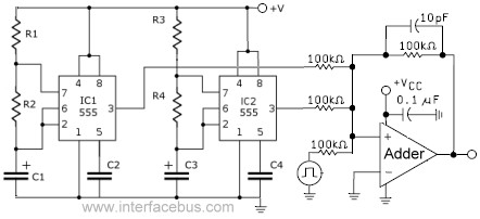
This circuit combines the outputs from two distinct 555 multivibrators using a summing operational amplifier (Op Amp). It serves to illustrate an alternative implementation of a 555 timer, with most background calculations addressed in other sections. The standard configuration...
This class-D audio amplifier is suitable for TV and home stereo systems. The TDA7882 integrated circuit (IC) provides a class-D audio amplifier solution. Since this IC has a single channel output, two units are required for stereo applications. The...