
PC FM Radio Circuit

To implement this system, the parallel port of the PC can be utilized to control the D/A converter, which translates digital signals into corresponding analog voltages. The program, written in one of the aforementioned programming languages, will iterate through a range of values from 0 to 255. Each value corresponds to a specific voltage output from the D/A converter.
The D/A converter's output is connected to a VARICAP diode, which is a type of variable capacitance diode. The capacitance of the VARICAP varies with the voltage applied across it, thus allowing control over the resonant frequency of an LC circuit in which it is integrated. By systematically changing the output voltage from the D/A converter, the program can effectively manipulate the frequency of the radio signal generated.
The parallel port communication involves setting the appropriate control and data lines to send the desired digital values. The program should ensure proper timing and synchronization with the D/A converter to achieve accurate voltage levels. Additionally, it may be necessary to implement error-checking mechanisms to handle any potential communication issues.
In summary, this setup combines programming, digital-to-analog conversion, and radio frequency modulation to create a versatile system capable of generating a range of frequencies based on user-defined inputs.If you know some language of programming as C +, PASCAL, VISUAL BASIC, DELPHI etc you can write a program which will send in the parallel door (378 I) of PC a number from 0 until 255 checking thus the tendency of expense of simple D/A of converter (that it is in blue frame) and consequently and frequency of radio via passage VARICAP. 🔗 External reference
Related Circuits
The count switching circuit consists of an electronic switch and a pulse delay circuit for control. The count switching circuit is designed to manage the switching of signals in a controlled manner. The electronic switch serves as the primary component...
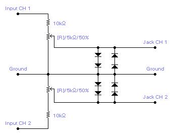
For simple electronic circuits, it may be sufficient to gain qualitative insights on dedicated electrical signals. This interface circuitry allows the line-in input of a standard PC sound card to be utilized as a 2-channel oscilloscope. Although this setup...
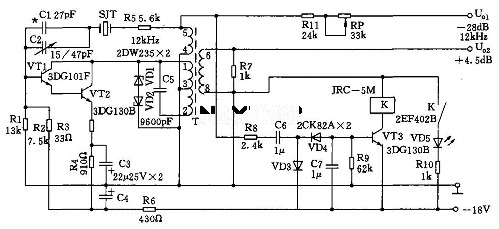
The circuit depicted is a 12 kHz intermediate frequency oscillator designed for an alarm system. It employs a variable feedback oscillation circuit where the oscillation frequency is primarily determined by a quartz crystal. Capacitors C1 and C2 are used...
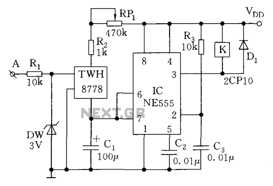
This is a voltage doubling circuit built using the well-known timer IC 555. The circuit is straightforward and easy to construct. The construction is not critical. Rectifier diodes should be ultrafast (such as UF4004 or similar), or 1N4148 signal...
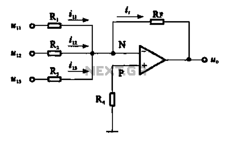
An adder circuit, specifically the inverting adder circuit, utilizes the inverting input of an operational amplifier to process signals. Voltage inputs are added through resistors connected to the inverting input terminal of the operational amplifier. The circuit configuration, as...
This circuit is designed to indicate, via a flashing LED, when room noise exceeds a predetermined threshold, selectable from three fixed levels: 50 dB, 70 dB, and 85 dB. The circuit utilizes two operational amplifiers to amplify the sound...