
Integrated digital volume potentiometer circuit

The volume and tone control circuit depicted in Figure 4-18 is designed to facilitate precise audio signal manipulation. The use of potentiometers Xi 153AP and 155AP allows for seamless adjustment of volume and tone, catering to user preferences in audio output. The oscillation frequency is determined by the clock elements Rx and Cx, which are integral for ensuring the stability of the circuit's operation. The formula provided for frequency calculation highlights the relationship between capacitance and frequency, enabling users to select appropriate values based on their specific requirements.
The attenuation levels are crucial for managing signal strength, with the Guardian 153AP providing a broad adjustment range. The specific resistance values associated with each attenuation step facilitate predictable changes in audio output, enhancing user control over the listening experience. The dual-channel configuration ensures that both left and right audio signals can be adjusted independently while maintaining a favorable signal-to-noise ratio, which is essential for high-fidelity audio reproduction.
The TC9155AP's design further enhances this circuit's capabilities by integrating dual identical circuits, allowing for fine-tuning of audio signals across a wider dynamic range. The inclusion of a 13-step adjustment mechanism provides users with granular control over audio output, enabling precise tailoring of sound characteristics.
The operational amplifier feedback loop, formed by connecting the electronic potentiometer network with an external capacitor, plays a vital role in the tone control circuit. The choice of operational amplifiers, such as the TA75558P or MC1458, is critical, as these components are known for their low noise and high performance in audio applications. This configuration ultimately results in an efficient and effective audio processing circuit, suitable for various audio applications, from consumer electronics to professional audio equipment.Figure 4-18 by volume potentiometer T (Xi 153AP and tone potentiometer T ( 155AP consisting of volume, tone control circuit circuit, Rx, cx clock oscillation element, the value of which can be selected according to the desired oscillation frequency : f (Fic L/. 0.7F xCx (Hz) where Rs 3Rxo Guardian 153AP adjustment method using the attenuation levels, the total attenuation adjustment range of O-66dB, unit step attenuation amount of the attenuation level which 2dBo use 10dB attenuation amount units (corresponding to the resistance value of 50 snapped that RATT1); the second level attenuation minus 2dB units using the amount of attenuation (corresponding to the resistance value 20kfl, namely RATT2) o have the same circuit two inner lc, respectively for left and right channel use. to obtain good signal to noise ratio can be used to input RArTl, RATI2 for output. TC9155AP built two identical circuits each t is an adjustment range of 6 ~ + 6dB, the resistance value of is 100kn, sub -level 13 step adjustment, each with a set of two-channel electronic potentiometer resistor network together with an external capacitor connected to the op amp s feedback loop amplifier, tone control circuit composed of feedback operational amplifier using TA75558P also be MC1458 or other similar operational amplifier circuit.
Related Circuits
To charge lead-acid batteries, a circuit can be utilized that consists of a current-limited power supply and a flyback converter topology. The circuit designed for charging lead-acid batteries incorporates a current-limited power supply alongside a flyback converter topology to...
A video digitizer, also known as a frame grabber, captures still picture frames from a television set, video camera, or video recorder, and transmits them to a computer for display, storage, or manipulation. This document outlines the Mark II...
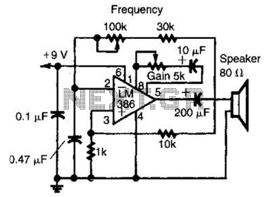
An LM386 audio power IC is configured as a feedback oscillator. It can operate with a supply voltage ranging from 6 to 12 V. The circuit is capable of driving a loudspeaker. The LM386 is a low-voltage audio power amplifier...
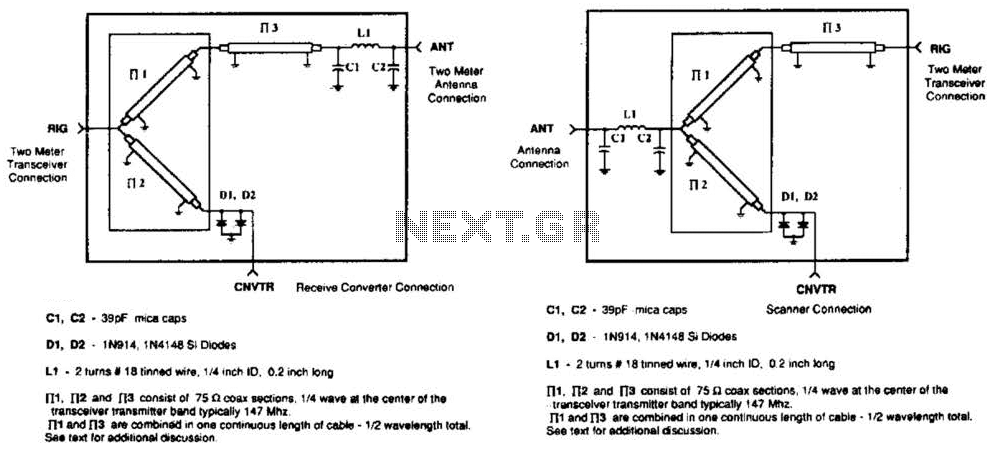
A pair of diodes and a quarter-wave transmission line are utilized as an automatic TR switch. D1 and D2 conduct during transmit periods, short-circuiting the scanner input. In this mode, the quarter-wave line appears as an open circuit. In...
The tank circuit consisting of capacitor C2 and inductor L1 is utilized to tune the transmitter. The antenna is coupled to the transmitter through capacitor C3 and can be either a telescopic antenna or a length of hookup wire....
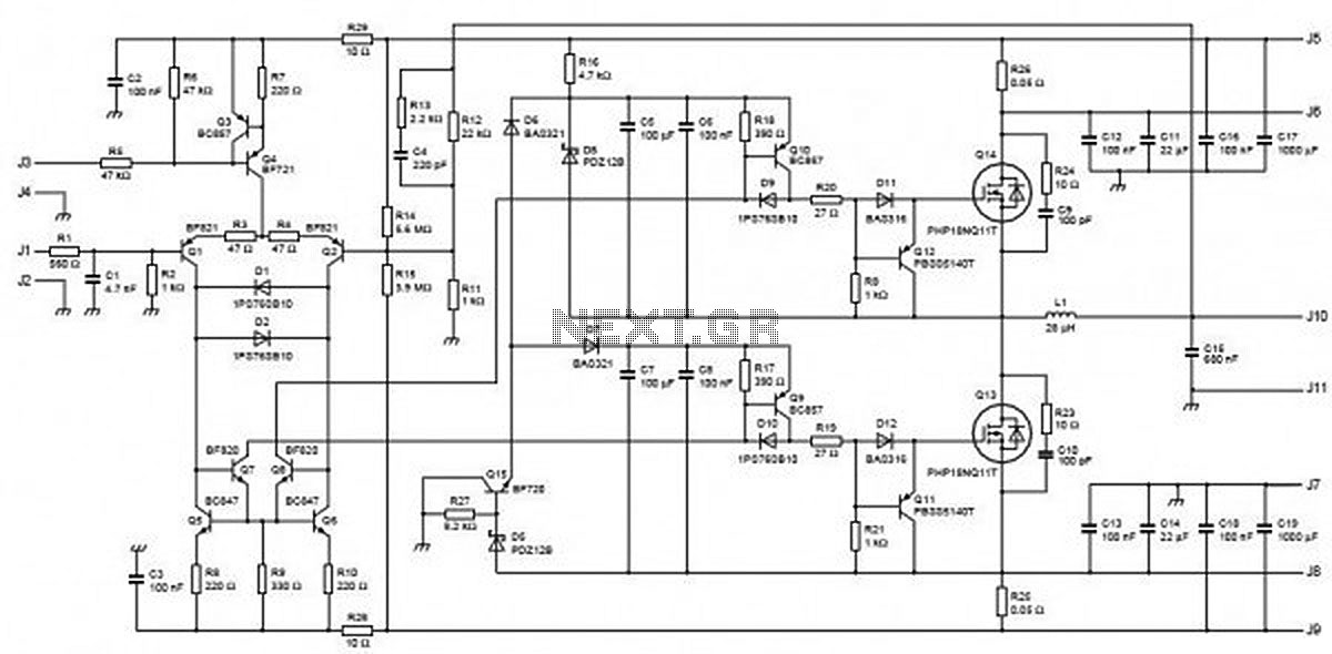
This circuit is capable of delivering approximately 200W of power output, produced by Phillips Semiconductor. It utilizes two PHP1BN11QT devices and operates with an input voltage range of 30 to 45 Volts DC. The described circuit is a high-power switching...