
TDA8560 class B power amplifier circuit design project

The TDA8560 is a versatile audio amplifier IC that operates efficiently in automotive environments. Its Class B design allows for reduced power consumption and heat generation while maintaining high fidelity audio reproduction. The fixed voltage gain ensures that the amplifier maintains a consistent output level, which is critical for achieving balanced sound across both channels.
The dual 40-watt output capability makes this amplifier suitable for driving speakers in a car audio system, providing ample power to deliver quality sound at various volume levels. The IC is designed to handle the typical load impedance found in car audio systems, ensuring compatibility with a wide range of speakers.
The built-in diagnostic features are particularly beneficial for maintaining system reliability. The distortion sensing mechanism allows the amplifier to detect when the output signal is approaching clipping, which can result in distortion. In such cases, the diagnostic output can signal an external sound processor or volume control to adjust the input signal, thus preventing damage to the speakers and maintaining sound quality.
Temperature monitoring is another critical feature of the TDA8560. When the operating temperature exceeds 150 °C, the amplifier automatically reduces its output or disables the signal to prevent thermal damage. This self-protecting mechanism enhances the longevity and reliability of the amplifier in demanding automotive environments.
Furthermore, the short-circuit protection feature ensures that the amplifier can withstand accidental shorts without sustaining damage. If a short-circuit is detected at the output, the amplifier will disable its outputs until the fault is cleared, safeguarding both the amplifier and connected speakers.
Overall, the TDA8560 audio amplifier IC is a robust solution for car audio applications, combining high power output, reliability, and advanced protection features in a single package.A very simple class B power amplifier can be designed using TDA8560 audio IC. The TDA8560 amplifier has an internally fixed voltage gain for excellent channel balance. This audio amplifier electronic project will provide a dual 40 watt output power. This audio amplifier IC is specially designed for car audio applications. A diagnostic facility s enses distortion, load short-circuit and temperature. At onset of distortion or temperature >150 °C, the diagnostic output signal can be used to reduce the input drive via a sound processor or DC volume control. For load short-circuit or output short-circuit to ground or supply, the outputs are switched-off until the short-circuit is removed.
🔗 External reference
Related Circuits
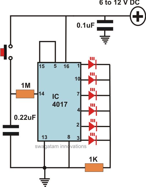
This article offers a circuit diagram and a discussion on CMOS logic and IC layout for creating a set of attention-getting LED running lights. It details a simple sequential LED flasher or light chaser that can be built, including...
Both halves of the circuit are identical. Both inputs have a DC path to ground via a 47k control, which should be a dual logarithmic type potentiometer. The balance control is a single 47k linear potentiometer, which, when adjusted...
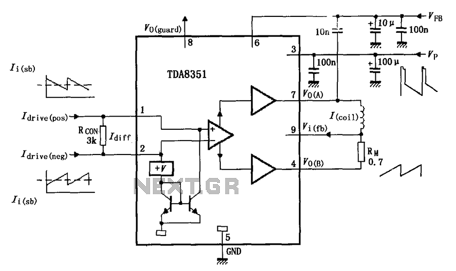
The figure illustrates the actual application circuit for the TDA8351/8356. In this circuit, a 50V voltage feedback (VFB) is connected in series with a 33-ohm resistor. Signals are input at pins 1 and 2, where pin 1 receives a...

This is a low-cost FM antenna booster designed to enhance reception of programs from distant FM stations. The FM antenna booster circuit features a common-emitter tuned RF preamplifier utilizing the VHF/UHF transistor 2SC2570 (C2570). The schematic illustrates the configuration...
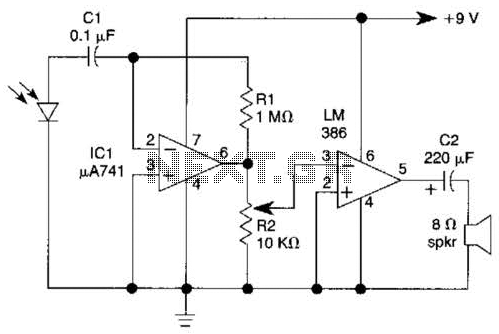
This light-wave receiver comprises a 741 operational amplifier functioning as a preamplifier and an LM386 operational amplifier serving as a power amplifier. The gain control is managed by a potentiometer labeled R2. Various types of detectors can be utilized...
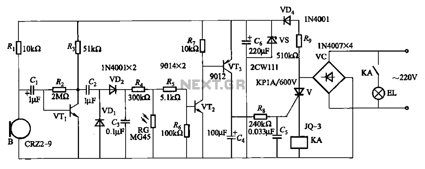
A resistor R8, capacitors Cd, and a thyristor V AC switch form a delay circuit. The lamp's lighting delay time is determined by the resistor Rs and capacitor C4, with a delay of approximately 40 seconds as indicated in...