
Stereo Preamplifier with adjustment tone

Additional Content: The preamplifier circuit mentioned is a highly functional and efficient design, utilizing the Motorola TCA5550 opamp. The TCA5550 is a versatile component that includes a dual amplifier, providing the ability to adjust various audio parameters such as volume, balance, treble, and bass. This feature makes the circuit adaptable to a wide range of audio applications.
The circuit's simplicity is highlighted by its minimal component requirement and ease of assembly, making it an ideal choice for both novice and professional electronics engineers. The use of monophonic linear potentiometers for parameter adjustment further simplifies the manufacturing process. These potentiometers are responsible for modifying the circuit's audio output characteristics, providing a high degree of control over the final sound output.
One crucial aspect of this circuit design is the placement of the potentiometers. They should be positioned as close as possible to the IC1 component. This strategic placement helps to minimize noise interference, ensuring a clean and clear audio output.
The circuit operates on a low current, making it energy-efficient and suitable for applications where power consumption is a concern. Despite its low power requirement, it delivers a robust performance, meeting the demands of various audio amplification needs.
Overall, this simple preamplifier circuit design, with its ease of manufacture, versatility, and energy efficiency, offers a reliable solution for various audio amplification applications.Many times we needed to use a simple circuit of preamplifier, with few components and facility of made. This circuit use a opamp. the Motorola, TCA5550, that contains a double amplifier, as outputs for the adjust of volume, balance, treble and bass.
These adjustment of all parameters become from a line monophonic linear potesometers, increasing by far the facility of manufacture. The placement these potesometers should become as much as possible, more near in IC1, so that is minimised the noise.
The circuit does not require big current in order to it work. 🔗 External reference
Related Circuits
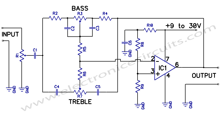
A preamplifier circuit featuring independent Bass and Treble tone controls is illustrated in this schematic. This circuit design utilizes operational amplifiers (op-amps) to achieve independent control over the bass and treble frequencies, allowing for enhanced audio customization. The preamplifier stage...
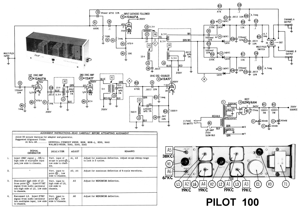
As the number of stations increased and the power levels also rose, receiver performance had to be enhanced. The pentagrid converter, such as the 6BE6 tube (British EK90 valve), was introduced, which was optimized for mixer performance. This included...
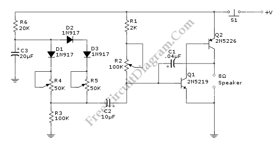
This doorbell circuit generates a low tone that transitions to a higher frequency. The total equivalent resistance connected between the base of Q1 and ground (Rbg), along with coupling capacitor C1, determines the frequency of the audio frequency (AF)...
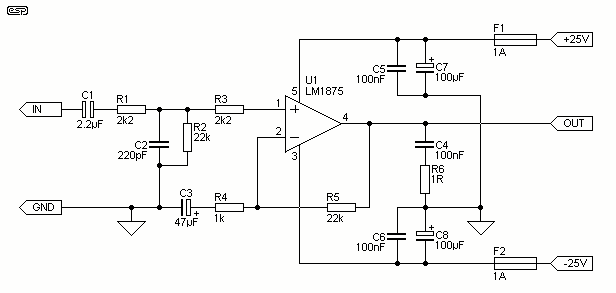
This project is based almost directly on the typical application circuit in the National Semiconductor specification sheet. You can also use the TDA2050 (from SGS-Thompson), which has almost identical performance and (remarkably) the same pinouts! As it turns out,...
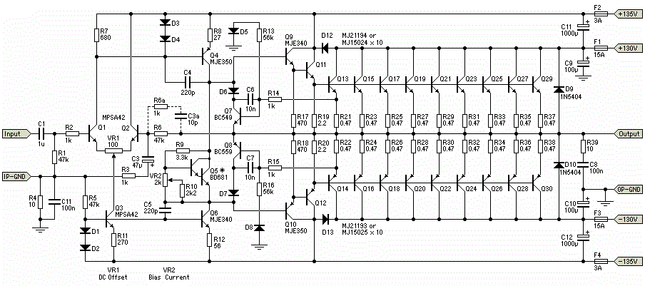
The circuit for the power amplifier has a power output of up to 1500W RMS and is commonly utilized in outdoor sound systems. The final image displays a series of power amplifiers that utilize 10 sets of power transistors....
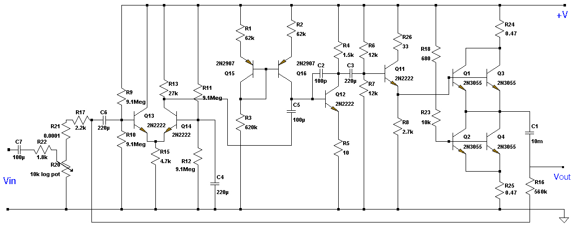
This Class A preamplifier features a symmetrical design. The input differential stages utilize dual transistors, T1 and T2. Polarization correction is crucial due to amplification discrepancies and is managed by transistor T12. Potentiometer P2 adjusts the output voltage to...