
A Ph Probe Buffer Amplifier

The buffer amplifier serves a critical role in interfacing high-impedance sensors, such as pH probes, with lower-impedance measurement devices or circuits. The high input impedance of the buffer amplifier ensures that the probe's output signal is not significantly affected by the load it drives. This characteristic is crucial when dealing with the delicate signals produced by pH sensors, which can be influenced by external factors if connected directly to measurement equipment.
The typical configuration of a buffer amplifier utilizes an operational amplifier (op-amp) in a voltage follower arrangement. In this setup, the output of the op-amp is connected directly to its inverting input, while the non-inverting input receives the signal from the pH probe. This configuration provides unity gain, meaning that the output voltage will be equal to the input voltage, effectively allowing the buffer to pass the signal without amplification or attenuation.
To ensure optimal performance, it is important to select an op-amp with a very high input impedance, low output impedance, and a wide bandwidth. This will help to maintain signal integrity and minimize any potential distortion or noise introduced by the amplifier. Additionally, power supply considerations should be taken into account to ensure that the op-amp operates within its specified voltage limits, which can vary depending on the specific application.
In practical applications, the buffer amplifier may also incorporate additional features such as filtering or gain adjustment, depending on the requirements of the measurement system. However, the primary function remains focused on isolation and impedance matching, providing a reliable interface between the pH probe and subsequent processing or display circuits.Buffer amplifier is required by a typical pH probe to isolate its 10^6 to 10^9 ohm source resistance from external circuitry. Such an amplifier is shown in the.. 🔗 External reference
Related Circuits
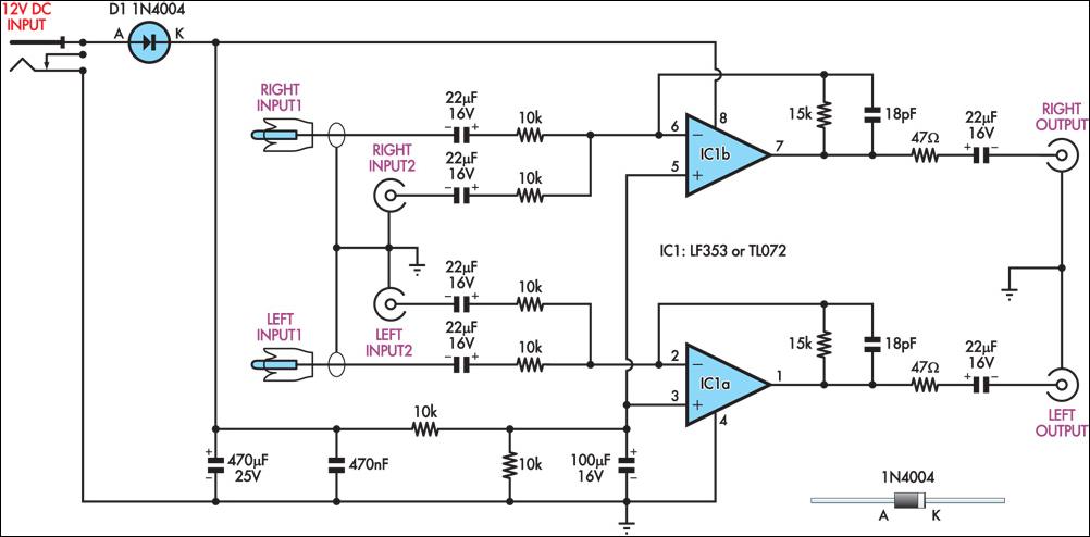
This circuit combines two separate line-level stereo (L & R) signals into one stereo (L & R) output, eliminating the need to switch between two pairs of input signals. It is utilized in a scenario where the stereo audio...
All resistors have a tolerance of 5 or 10 percent and are rated for 1/4 watt. All capacitors have a tolerance of 10 percent and are rated for 35 volts or higher. This circuit effectively amplifies the output of...
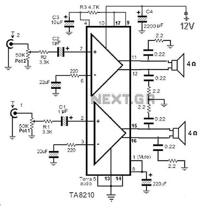
This circuit consists of a 2 x 22 watt BTL amplifier utilizing the IC TA8210AH. It functions not only as an automobile amplifier but is also suitable for low-frequency sound applications, particularly in high-fidelity audio systems, due to its...
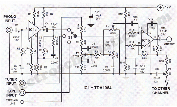
This Hi-Fi stereo preamplifier circuit is designed using the TDA1054 integrated circuit from SGS. The TDA1054 is a 16-pin DIL package that incorporates two separate preamplifier circuits. It is a low-noise preamplifier with minimal complications in the design process....
This is a 25-watt basic power amplifier designed for ease of construction at a reasonable cost. It offers superior performance compared to standard STK module amplifiers commonly found in most mass-market stereo receivers produced today. The 25-watt basic power amplifier...
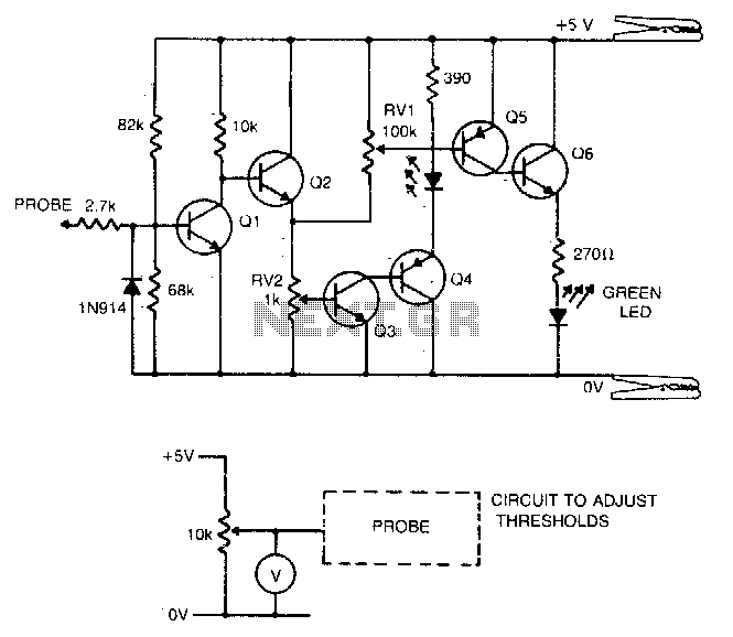
Transistors Q1 and Q2 create a buffer that offers the probe a suitable input impedance. Q3 and Q4 constitute a level detection circuit. When the voltage across the base-emitter junction of Q3 exceeds 0.6 V, the transistor activates, which...