
A constant current source of the differential amplifier circuit

A constant current source circuit is critical in ensuring the stability and performance of differential amplifiers. In this design, the differential amplifier employs an emitter resistor to set the operating point and improve linearity. The constant current source, implemented using a transistor (VT3), plays a pivotal role in maintaining a steady current through the amplifier, regardless of variations in load or supply voltage.
The transistor VT3 is configured to provide a bias voltage that keeps the differential amplifier in its active region, which is essential for linear amplification. As input signals cause fluctuations in the potential at the base of VT3, the circuit dynamically adjusts to maintain a constant current. When the output voltage (Ua) increases, it is necessary to control the supply voltage (Ucc) to prevent undesired increases in output. The design ensures that as the voltage across the emitter resistor (I * 3Re) increases, the current through the transistor is regulated to prevent any drift in the output signal.
This feedback mechanism is crucial for maintaining the performance of the amplifier, particularly in applications where precision is required. By suppressing variations in the current (Si), the circuit effectively mitigates zero drift, ensuring that the amplifier operates consistently over time. The careful selection of the emitter resistor value and the characteristics of the transistor used in this configuration are vital for achieving the desired performance metrics, including bandwidth, noise performance, and linearity. The overall design emphasizes the importance of stability and accuracy in differential amplifier circuits, making it suitable for a wide range of electronic applications.A constant current source of the differential amplifier circuit (2) having a constant current source of the differential amplifier with emitter resistor in differential amplifi er, where larger, a Ua also increases, which is not appropriate. In order to make every time increases, Ucc can be lower, triode available, this circuit is called a constant current source transistor of the differential amplifier, as shown in FIG. Figure, s, played a role in the partial pressure for VT3 base provides a bias voltage to work in the enlarged state.
How it works: When the potential of the rise, Si, Si increases, the voltage across I * 3Re should be increased, but remained unchanged Gong, forcing U. Decreases, so that the island is reduced, causing reduced Si, such as the rise is suppressed to maintain the constant 3, and this is the role of the constant current source of the transistor VT3.
Si unchanged, Si suppressed, as can not be increased, so as to suppress the zero drift.
Related Circuits
This preamp is very simple, and will work under tough conditions. The input impedance is pretty high, so it won't load down electric guitars. It will also amplify microphones. When there is a moment, there will be some additions that...
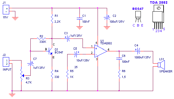
A small amplifier with nice characteristics: Tendency of catering: 15V. Force of expense: 4.2Wrms in the 4W. Minimal signal of entry: 94mVp-p with preamplifier, 0.65Vp-p without the preamplifier. More: Materially: R1=2.2kΩ R2=330kΩ R3=4.7kΩ logarithmic potentiometer R4=330Ω R5=1kΩ R6=1.5Ω C1,...
The TDA2005 integrated circuit (IC) features a high output power of 10W per channel (stereo) at a load of 2 ohms with a distortion of 10%, and 20W in bridge mode at a load of 4 ohms with a...
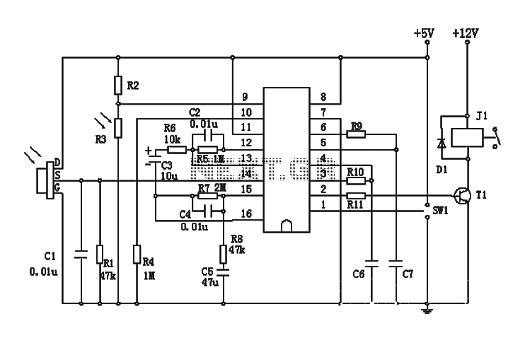
The BISS0001 is a high-performance integrated circuit designed for sensor signal processing. When combined with pyroelectric infrared sensors and a minimal number of external components, it forms a passive pyroelectric infrared switch. This device can automatically and quickly activate...
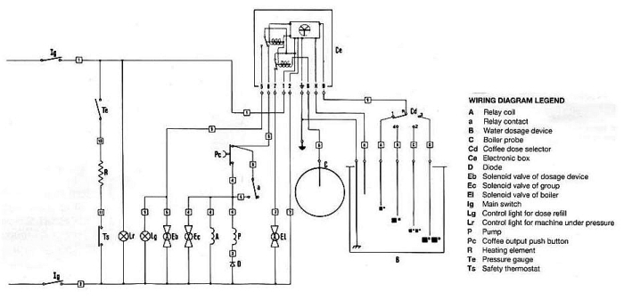
The pump is designed to stop only when the volume set by the four-position selector switch has been reached. However, it will also stop if certain conditions are met. Pressing the brew button (`Pc`) momentarily closes the circuit, sending...
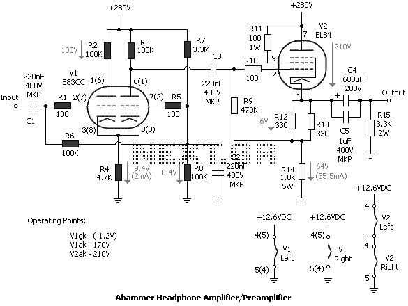
Tube amplifiers designed for headphones have the principal property that they can be used as preamplifiers too. In most cases, the output impedance of a tube headphone amplifier is (or should be) less than the output impedance of a...