
A DC motor PWM speed control circuit

Most governors in electronic circuits employ pulse width modulation (PWM) and pulse position modulation (PPM) techniques for efficient control of motor operations. The 555 timer IC is a prevalent choice for generating precise timing intervals in these applications. In standard configurations, the pulse width is set to a fixed duration of 0.5 milliseconds, which is critical for the reliable operation of various motor starters.
The pulse duration is a vital parameter, particularly when interfacing with electric machines, where a pulse width of approximately 5 milliseconds is often sufficient for effective control. The frequency of the PWM signal, which is influenced by the resistor-capacitor (RC) network within the circuit, determines the discharge time of the 555 timer. By varying the resistance values in the network, the discharge time can be adjusted, thereby affecting the revolutions per minute (RPM) of the connected motor.
The pulse interval can be manipulated to achieve a range of operational speeds, typically from 1 to 14 milliseconds. This flexibility allows for a wide spectrum of motor speed control, adapting to various application requirements. When a thermal resistor of 20kΩ is incorporated into the circuit, alongside a motor rated at 12V and 6A, the design can efficiently regulate the motor's performance, ensuring smooth operation and responsiveness to control signals. This configuration is particularly useful in applications requiring precise motor control and speed regulation.Dong Fang Zhuo most governors are pulse width modulation, pulse position modulation DA foot of the circuit (the clock when called righteous side of the system). Manifold 555 ov er-prescription contact Hajime Watanabe modulator ( lose foot mountain pulse width is fixed ff 0.5 ms (when thirty towel holder 0. I normally respect the decision). Thus, creeping pulse duration are f by the electrical machine connected to exhaust 05 ms. this is sufficient to pity, especially when the majority of motor starters, ianlwa last turn depend upon compliance pulses ask every time interval shorter shutter speed higher, this time interval err delete namely Cn by f, R.
lc, DIS to end (7 feet) discharge time. Therefore, adjusting Pi 0 change the discharge time that is r eight consecutive section built motor revolutions. then shown around the element in what number, collapse f Sh pulse interval may be as I - 14 milliseconds, therefore, Quine section motor speed range is quite wide, if installed in the L N thermal 20k /.
W of the radiator L. circuit can be controlled collapse straight 12V/6A of splashing motor.
Related Circuits
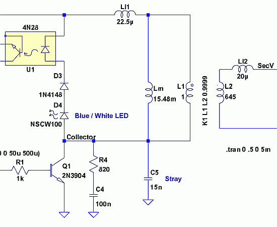
The 1-megohm resistor protects the FET from potential damage caused by accidental sparks to its gate lead. The circuit functions adequately without this resistor; however, it is advised not to intentionally apply a charge to the gate wire using...
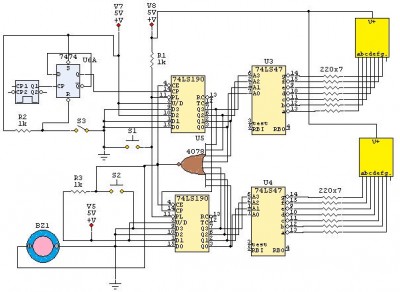
This is a 24-second countdown timer circuit designed for automatic control of electronic loads. The timer circuit utilizes fast 74LS Schottky integrated circuits (ICs). A 24-second countdown begins when switch S3 is off and switch S2 is pressed. Switch...
Thanks to the S6986, the circuit is very simple and requires few components. D2, D3, D5 and D6 forms a bridge rectifier allowing to plug the sensor connector brick in any direction. C1 filters power supply, it must be...
Since then, NL has evolved into the Microsoft Windows®-based NL4, which has been extensively used by world-class engineers in various fields of electronics for almost 10 years. NL5 is the first version to be publicly available. Unlike conventional SPICE-based...
The circuit involves powering an LED using a 3V CR2032 battery, with the intention of extending battery life by making the LED blink rather than remain continuously on. A 555 timer is considered, utilizing large value resistors in the...

The circuit illustrated here demonstrates that, despite advancements in components and technology, it remains possible to design effective and intriguing circuits. This design utilizes two well-known transistors, the BF256C and the BF494. Along with the necessary resistors and capacitors,...