
Laser Target Finder circuit

The circuit utilizes the Hamamatsu S6986 sensor, which is crucial for high-performance light detection applications. The design incorporates a bridge rectifier formed by diodes D2, D3, D5, and D6, which ensures that the sensor can be connected in either orientation, thus enhancing user convenience and flexibility. The bridge rectifier effectively converts AC voltage to DC, providing a stable power source for the sensor.
Capacitor C1 plays a vital role in filtering the power supply to the S6986, minimizing voltage fluctuations and ensuring that the sensor operates under optimal conditions. It is critical that C1 be placed in close proximity to the S6986 (IC1) to effectively bypass any high-frequency noise that may affect performance.
The S6986 sensor operates by emitting a laser beam at a 1/16 duty cycle. The photodiode integrated within the sensor is responsible for detecting the light reflected from the target. The internal processing circuitry of the S6986 compares the intensity of the emitted light to the intensity of the received light. This correlation allows for reliable detection of targets even in environments with significant ambient light interference.
When the S6986 detects a sufficient level of reflected light, its output signal transitions to a low level, indicating that the target is within the laser beam. Resistor R1 serves to limit the current flowing from the output of the S6986, protecting the downstream circuitry from excessive current that could potentially cause damage. The output from the S6986 is a boolean signal, providing a clear indication of whether the target is detected or not, facilitating straightforward integration into larger systems, such as an RCX sensor input.Thanks to the S6986, the circuit is very simple and requires few components. D2, D3, D5 and D6 forms a bridge rectifier allowing to plug the sensor connector brick in any direction. C1 filters power supply, it must be connected near to IC1 to bypass it properly. IC1 is the Hamamatsu S6986 sensor, the "heart" of this sensor. LED output drives the laser with a 1/16 duty cycle, and the included photodiode collects reflected light.
Internal processing circuitry correlates the received light to the emitted light, this enables very reliable detection even with high ambient light. When S6986 receives enough reflected light, its output goes to the low level (R1 limits the current), and the RCX sensor input becomes "true". Note that this sensor only returns a boolean value, "true" if the target is in laser beam, & 🔗 External reference
Related Circuits

The intelligent control circuit for the iron is presented. This circuit utilizes the integrated circuit PT8A351X to manage functions such as direction detection, relay control, and LED indication. When the iron is positioned horizontally, it will power off after...
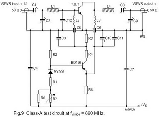
The circuit is designed for driving small UHF TV transmitters, providing a gain of 7 dB and capable of amplifying signals within the frequency range of 470-860 MHz. Key components include resistors, capacitors, and transistors. This circuit serves as a...
This is a silicon transistor circuit showing typical voltage values. When the forward base/emitter voltage is 0.6 to 0.7 V, the transistor is silicon. Germanium transistors will have a forward base/emitter bias voltage of 0.2 to 0.3 V. This...
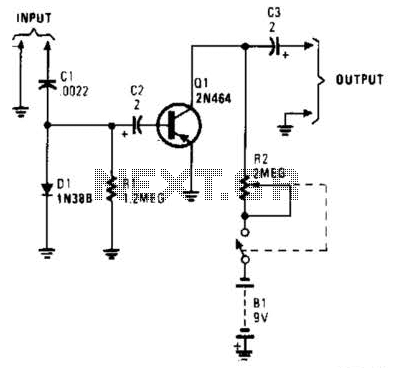
In this circuit, C1, D1, and R1 form an envelope detector. C2 couples audio to the base of Q1. R2 can be adjusted for the desired gain. The circuit under discussion utilizes an envelope detector, which is a fundamental component...
The circuit comprises an N-MOSFET voltage follower (T1, common drain) and a current source (T2, NPN Darlington). The current source is set to 2.2 Amps. With a supply voltage of 40V, the circuit can deliver approximately 17W into an...
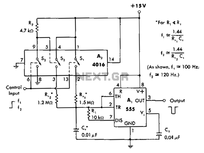
A circuit diagram controls the timing based on the input line state. When the input line is high, the 4016 CMOS analog switches select the timing of a 1.5 megohm resistor (Rt1) to produce negative output pulses at a...