
A digital display timer circuit diagram

The digital timer circuit operates by utilizing a pulse signal generated by an oscillator or clock circuit. This pulse signal serves as the time base, which is essential for counting time intervals accurately. The time counter is typically implemented using flip-flops or binary counters, which increment their count with each pulse received from the oscillator.
The digital decoders are responsible for converting the binary output from the time counter into a format suitable for the display unit. Commonly, a 7-segment display is employed, where each segment corresponds to a specific binary input. The decoder translates the binary count into the appropriate segments to illuminate, thus visually representing the elapsed time.
The overall accuracy of the digital timer can be influenced by several factors, including the stability of the oscillator, the precision of the time counter, and the quality of the digital decoders. To enhance accuracy, it is advisable to use high-frequency oscillators and well-calibrated counters.
In practical applications, digital timers are widely used in various fields, including industrial automation, laboratory experiments, and consumer electronics. The design of the circuit can be tailored to meet specific requirements, such as adjusting the time base for different time intervals or incorporating additional features like alarm functions or countdown capabilities.
The schematic representation of this digital timer circuit would include the oscillator circuit, the time counter, the digital decoder, and the display unit, clearly indicating the connections and component values necessary for proper operation. Each component's role within the circuit is crucial for ensuring that the timer functions accurately and reliably.Digital timers with a display clear and precise features. It is a number that represents the time after the pulse signal by decoding the digital device with digital display tub e display. The circuit described is a digital display of the digital timers, its display unit according to the unit time base signal may be. It can be a second, can be divided, of course, also be time. But for a number of explicit timers, the when this unit too, due to this circuit structure, not easy to achieve accurate, it is seldom used.
Its circuit as shown in FIG. The base signal generated by the generator circuit, the time counter, digital decoders and digital display components.
Related Circuits
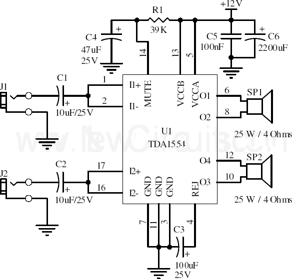
This document presents a 22-watt stereo audio power amplifier circuit diagram utilizing the TDA1554 integrated circuit from NXP Semiconductors (formerly known as PHILIPS Semiconductors). The circuit is designed to amplify stereo signals effectively. It dissipates approximately 28 watts of...
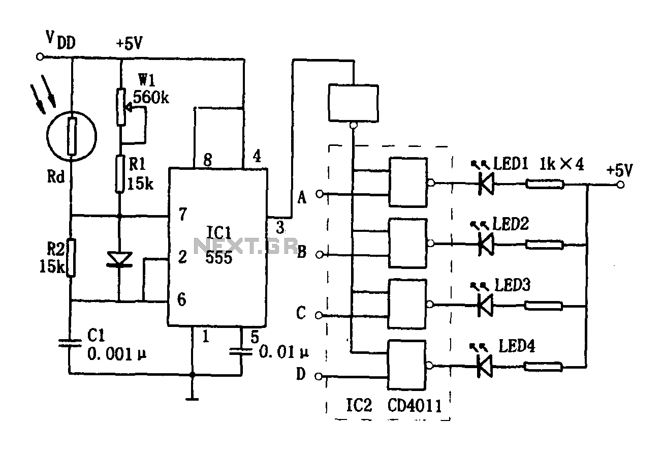
The brightness display circuit consists of a light-sensitive sensor, an oscillation circuit, and an LED display circuit. The light-sensitive sensor is a photosensitive resistor (Rd). The multivibrator is composed of Rd, R1, W1, R2, and C1, along with a...
This is a VU meter analog circuit. The circuit is connected to the line terminals of the amplifier. The VU meter operates simply, with T1 and T2 indicating signal increases. The VU meter circuit is designed to visually represent audio...
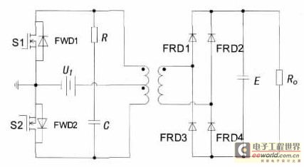
With the increase in the variety of modern electrical equipment for vehicles and the rise in power levels, there is a growing demand for different types of power supplies, including AC and DC sources. The power system needs to...
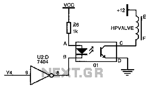
The driver circuit for the high-pressure natural gas shut-off valve utilizes solid-state relays. In dual-fuel mode operation, the fuel switching mechanism is controlled by a logic section that activates Y4 to a high state via U2 (7404 inverters). This...
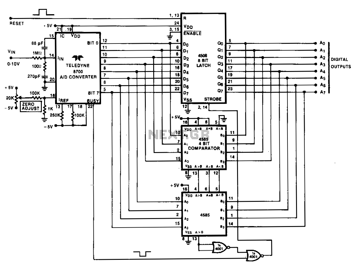
Analog peak detection is achieved by repeatedly measuring the input signal with an A/D converter and comparing the current reading with the previous reading. If the current reading is larger than the previous one, the current reading is stored...