
Simple vu Meter Analog Circuit

The VU meter circuit is designed to visually represent audio signal levels, providing a useful tool for monitoring sound output in audio applications. The circuit typically employs a moving coil meter, which is calibrated to respond to the average level of the audio signal rather than its peak values.
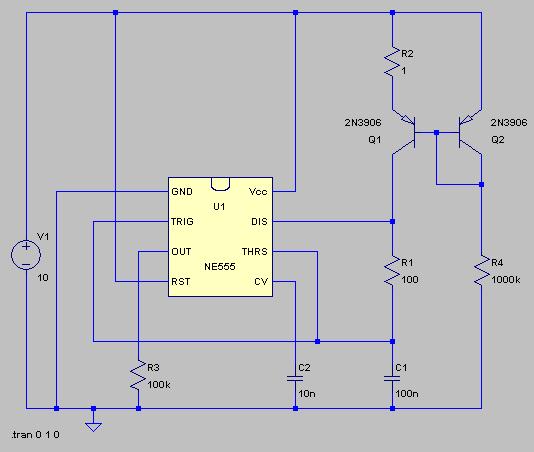
In this configuration, T1 and T2 are crucial components that serve as signal level detectors. They are often transistors or operational amplifiers that amplify the audio signal before it is fed to the meter. The connection to the amplifier's line terminals ensures that the circuit can accurately measure the output signal, allowing for real-time monitoring.
The circuit may also include resistors and capacitors that form a low-pass filter, smoothing out rapid fluctuations in the audio signal to provide a more stable reading on the VU meter. The meter itself is typically calibrated in decibels (dB) to provide a standardized reading of the audio level.
Furthermore, to enhance the functionality of the VU meter, additional features such as LED indicators or a peak hold circuit can be integrated. These features improve visibility and allow for better interpretation of the audio levels being monitored.
Overall, the VU meter analog circuit is a fundamental tool in audio engineering, enabling users to maintain optimal sound levels and ensure high-quality audio output.Here is vu meter analog circuit. The circuit is left connected to the line terminals of the amplifier. The VU meter is quite simple. T1 and T2 signal increase 🔗 External reference
Related Circuits
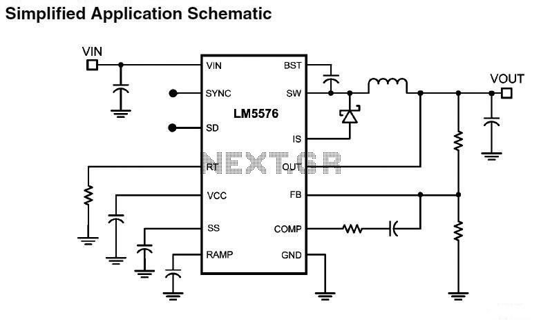
LM5576MHX absolute maximum ratings: (1) VIN to GND: 76V; (2) BST to GND: 90V; (3) PRE to GND: 76V; (4) SW to GND (Steady State): -1.5V; (5) BST to VCC: 76V; (6) SD, VCC to GND: 14V; (7) BST...
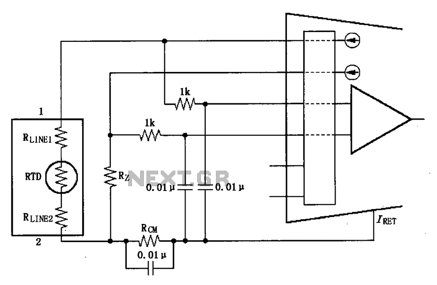
The long wire current loop transmission is susceptible to radio frequency (RF) interference, which can lead to errors in the sensitive input of the XTR108. This interference can occur particularly when the RTD sensor is located at a distance,...
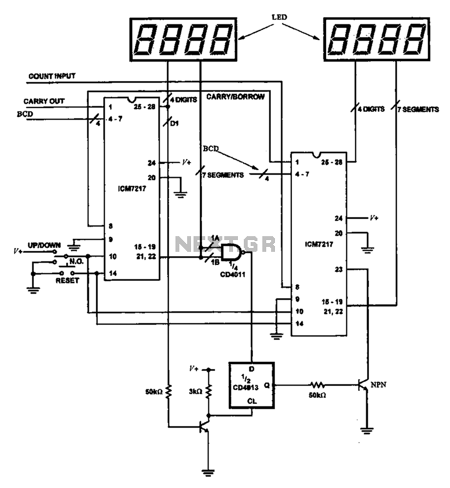
Figure 8 illustrates a potential digital counter circuit. This circuit employs two ICM7217 integrated circuits, with each controlling four digital display tubes. The digital counter circuit primarily utilizes the ICM7217, a highly integrated chip designed for driving seven-segment displays. Each...
Typically, when a car door is closed, the dome light turns off immediately. This circuit allows the dome light to gradually fade in brightness before eventually turning off. An electronic transformer dims halogen lamps and is a straightforward device...
The typical BPM range for music is between 40 and 240 BPM, corresponding to periods of 1500 ms and 200 ms, respectively. A BPM of 120 equates to a period of 500 ms. The circuit requires a resistor R4...
This DC voltage doubler circuit generates a voltage that is double its supply voltage. It is beneficial when a higher voltage level is required from a single power source. The DC voltage doubler circuit typically employs a combination of capacitors...