
A Dozen Small Cmos Alarm Circuits

The described CMOS alarm circuits are designed for versatility and efficiency, catering to a range of applications beyond mere alarm functionality. Each circuit is compact and can be printed on A4 paper, facilitating easy access and implementation. The low standby current is a critical feature, enabling prolonged battery life, which is essential for portable or remote applications where power availability is limited.
The inclusion of a flexible switch option allows for customization based on user needs. For instance, if a magnetic-reed switch is preferred for a security application, it can be easily integrated without altering the fundamental circuit design. The option to use multiple switches enhances the adaptability of the circuit, making it suitable for various configurations, such as multi-zone alarms or different triggering mechanisms.
The output mechanism, primarily a piezo buzzer, is chosen for its low power consumption and high sound output, making it effective for alerting users. The alternative of using a relay opens up further possibilities, such as activating larger devices or integrating the alarm system into existing home automation setups. Care must be taken to ensure that the relay coil's current draw remains within the specified limits to protect the driving transistor from damage.
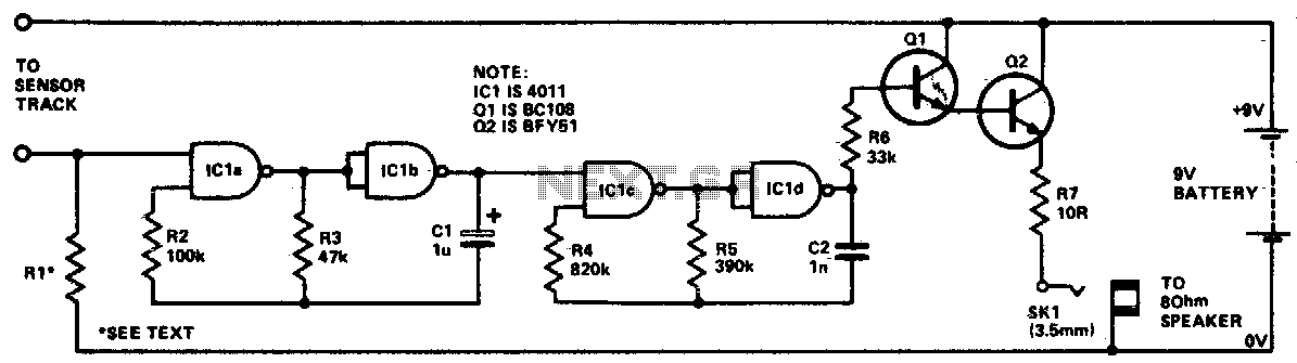
Overall, these small CMOS alarm circuits represent a practical solution for users seeking customizable, efficient, and low-power alarm systems that can be adapted for multiple applications.A Dozen Small Cmos Alarm Circuits Circuit Description This is a selection of small self-contained alarm circuits. The main features of each alarm are described on the circuit diagram itself. They all have a very low standby current. So they This is a selection of small self-contained alarm circuits. The main features of each alarm are desc ribed on the circuit diagram itself. They all have a very low standby current. So they are ideal for battery operation. Each pair of circuits will print out on an A4 sheet. Although they are described as alarm circuits - they will have other applications. Sw1 is drawn as either a micro-switch or a magnetic-reed contact but - so long as it does the job - you can use whatever type of switch you like. Use more than one switch if it suits your application. The output device is a "piezo" buzzer - requiring a current of about 10mA. But - you can replace it with a relay - and use the relay contacts to switch whatever device you like.
Just make sure that the relay coil doesn`t draw more than about 50mA - otherwise the transistor might be overloaded. 🔗 External reference
Related Circuits

This LED series will blink alternately. The operation is determined by the NE555 integrated circuit, with transistors used to reinforce each section (20 upper, 20 lower) for optimal performance. The 555 circuit described below functions as a flashing bicycle...

It is advisable to prototype the entire circuit using a breadboard. This method simplifies the process significantly compared to attempting to determine the connections on a small printed circuit board. Prototyping a circuit on a breadboard allows for easy modifications...

The core of the circuit is a two-transistor flasher with frequency modulation applied to the base of the first transistor. When the pushbutton is pressed, the oscillation frequency increases to a peak, and upon release, the frequency decreases due...

This alarm circuit is based on two 555 timers. The alarm will sound your car horn if anyone opens the car door while the circuit is armed. The timers will allow you to leave the car without sounding the...
The circuit utilizes four NAND gates from a 4011 package. In each oscillator, one gate functions as a simple inverter, while the other features a control input. The oscillator's operation is disabled when this input is held low. The...

The program utilizes the internal 4 MHz oscillator of the PIC16F628 microcontroller in a two-input alarm circuit. The two-input alarm circuit designed with the PIC16F628 microcontroller leverages the internal 4 MHz oscillator to provide a stable clock signal for operation....