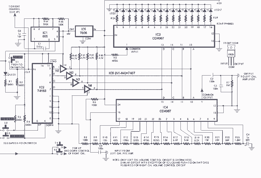
Small Strobe Light 555 astable multivibrator circuit

It is advisable to prototype the entire circuit using a breadboard. This method simplifies the process significantly compared to attempting to determine the connections on a small printed circuit board.
Prototyping a circuit on a breadboard allows for easy modifications and troubleshooting, as components can be inserted and removed without soldering. The breadboard consists of a grid of holes that are interconnected in specific patterns, enabling the user to establish complex circuits quickly.
When assembling the circuit on a breadboard, begin by identifying the essential components, such as resistors, capacitors, integrated circuits, and power sources. Place the power supply connections on the designated power rails of the breadboard, ensuring that the voltage levels are appropriate for the components being used.
Next, insert the components into the breadboard according to the circuit schematic. It is crucial to maintain proper orientation for polarized components, such as electrolytic capacitors and diodes, to avoid damage. Use jumper wires to make connections between the components, following the schematic layout closely to ensure functionality.
Once the components are in place, verify all connections before powering the circuit. This step helps to prevent potential short circuits or component failures. After powering the circuit, observe its operation and make any necessary adjustments. This iterative process of testing and modifying is one of the key advantages of using a breadboard for circuit prototyping.
In conclusion, breadboarding is a highly effective method for developing and testing electronic circuits, providing flexibility and ease of use that is not achievable with a traditional printed circuit board.I recommend breadboarding the entire circuit first. It was way easier on a breadboard that trying to figure out what goes where on a tiny piece of pr.. 🔗 External reference


