
A DSP Based Class D Audio Amplifier

Class D amplifiers are increasingly favored in audio applications due to their high efficiency, which can exceed 90% under optimal conditions. This efficiency is largely attributed to the switching nature of the output transistors, which operate in saturation or cutoff, significantly reducing the heat generated compared to linear amplifiers. The implementation of the TMS320F2808 digital signal controller allows for precise control of the PWM generation and the ADC sampling, facilitating the accurate reproduction of audio signals. The low-pass filter following the output stage is critical, as it smooths the PWM signal into a continuous analog waveform, effectively removing unwanted high-frequency artifacts created during the switching process. The design considerations for the low-pass filter include selecting appropriate resistor and capacitor values to achieve the desired cutoff frequency, typically just above the maximum audio frequency of interest (e.g., 20 kHz), ensuring that the audio signal is preserved while high-frequency noise is attenuated. The H-bridge configuration enables the Class D amplifier to drive speakers in both directions, allowing for full-wave operation and improved audio fidelity. The synchronization of the PWM signals ensures that the switching of the transistors occurs in a manner that maximizes efficiency while minimizing distortion, resulting in high-quality audio output. The system's architecture is conducive to scalability, allowing for integration with various audio sources and the potential for advanced features such as digital signal processing (DSP) for further enhancement of audio quality.A lens is a custom view of the content in the repository. You can think of it as a fancy kind of list that will let you see content through the eyes of organizations and people you trust. Summary: Class D amplifiers have proven a higher power efficiency performance against linear classes such as Class A, B and AB.
Power losses on Class D amplifier s are mainly due to non-ideality of the output transistors, operating as switches, controlled by Pulse Width Modulators. This example describes a method for utilizing both the Enhanced Pulse Width Modulator (ePWM) and the Analog-to-Digital Converter (ADC) of the TMS320F2808 digital signal controller as D-Class Audio amplifier.
The method involves analog full bridge D-class power amplifier and analog low-pass filtering the amplified PWM signal to remove high frequency components, leaving only the audio-frequency content. Class D amplifiers have proven a higher power efficiency performance against linear classes such as Class A, B and AB.
Power losses on Class D amplifiers are mainly due to non-ideality of the output transistors, operating as switches, controlled by Pulse Width Modulators. This example describes a method for utilizing both the Enhanced Pulse Width Modulator (ePWM) and the Analog-to-Digital Converter (ADC) of the TMS320F2808 digital signal controller as D-Class Audio amplifier.
The method involves analog full bridge D-class power amplifier and analog low-pass filtering the amplified PWM signal to remove high frequency components, leaving only the audio-frequency content. This block interfaces with the audio source, attenuates it DC component and limits the input voltage to the ADC to the range 0 - 3.
3V. The circuit contains also a DC-DC converter, for the DSP input buffer. The TMS320F2808, converts the analog signal to a pair of PWM signals that feed the output stage (Please refer to section ). It operates with 100 MHz. The ADC samples the input signal at a 97. 656. 25 Ksps rate. The ePWM, generates PWM signal with a period of 102. 4 s and duty cycle proportional to the input signal level. The ePWM coupled with a D-Class output stage and a second order passive RLC filter, provides a DAC equivalent.
The analog signal is converted to PCM values as shown in. The conversion is performed as described in Table 1. The ADC operates in a sampling rate of 97. 656 KHz (100 MHz/1024). The PCM values are converted to PWM as shown in Figure 4. A period of 102. 4 msecs (1024 clock cycles) was chosen. The relation PCM Value/Full Range is translated to the duty cycle of the PWM. A duty cycle of 512 (50 %) corresponds to 50% of the full range, for example. In this example sample values in the range 0-4095 will be mapped to duty cycle values (CMPA) in the range 0-1023, by dividing by 4 (shift right 2 bits), as shown in Figure 5. The process described in the previous section is executed in the Interrupt Service Routine (ISR). The ADC conversion is triggered by the ePWM block when the PWM period starts (every 102. 4 msecs). The ADC generates an interrupt at the end of conversion. The interrupt service routine updates the PWM duty cycle (CMPA value) on the value of this sample. The new duty cycle will be loaded in the beginning of the next PWM period. The process is described in Figure 6. This module contains the H-bridge, and a Low Pass Filter to remove high frequency components, leaving only the audio-frequency content.
This module basically implements a Digital to Analog Converter using a PWM signal generator and a Low Pass Filter as shown in. This method is described in. The basic configuration of a D-Class amplifier is the Half-Bridge (H-Bridge) configuration. Two output transistors operate as switches, driven by complementary PWM signals. One of the transistors is off (current through it is close zero), while the remaining one is on (voltage across it is close to zero), keeping the power dissipation very low.
The full-bridge Class D amplifier comprises two half bridges, driven by synchronized PWM signals, having two alternate conduction paths through the load, each one having a pair of transistor conducting while the remaining pair is off. 🔗 External reference
Related Circuits
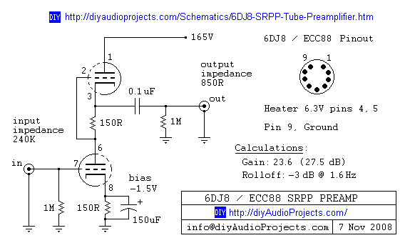
6DJ8 / ECC88 Symmetrical SRPP Tube Preamplifier Schematic. The gain of the preamp is 27 dB (approximately 23.5 times). The 6DJ8 / ECC88 symmetrical SRPP (Shunt Regulated Push-Pull) tube preamplifier schematic is designed to provide a high level of gain...
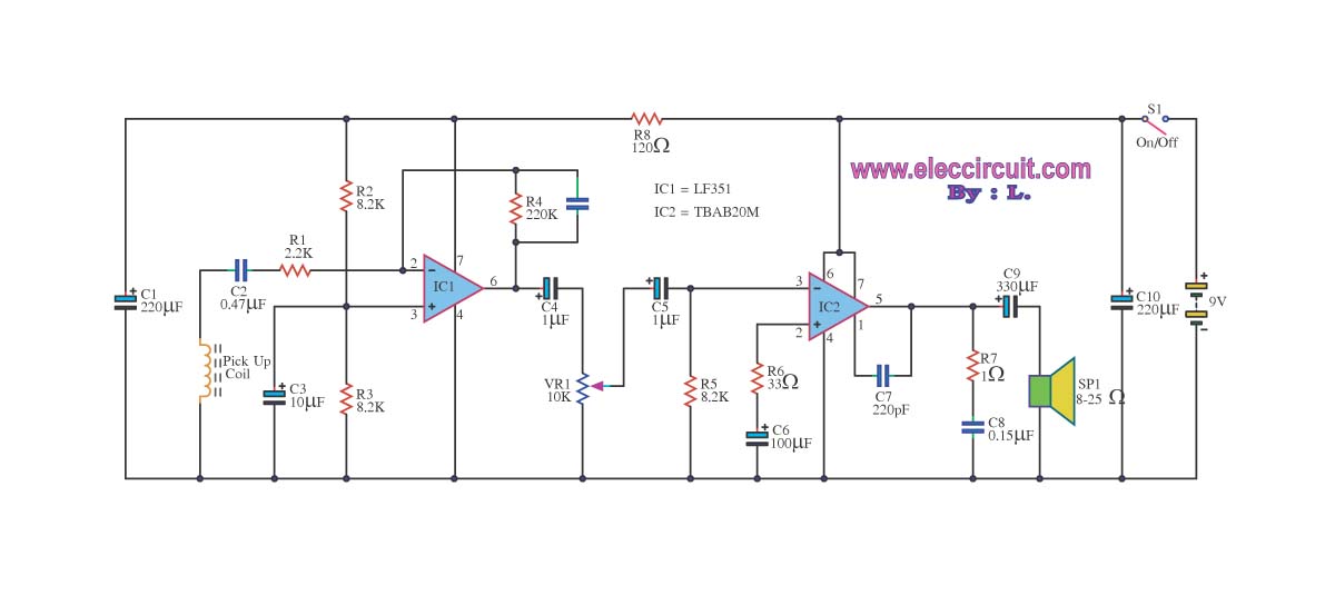
The circuit is designed to amplify telephone signals using a 2W+2W amplifier with an 8-ohm loudspeaker. It provides adequate sound output while maintaining good audio quality. The primary component of this telephone amplifier circuit is the IC LF351, which...
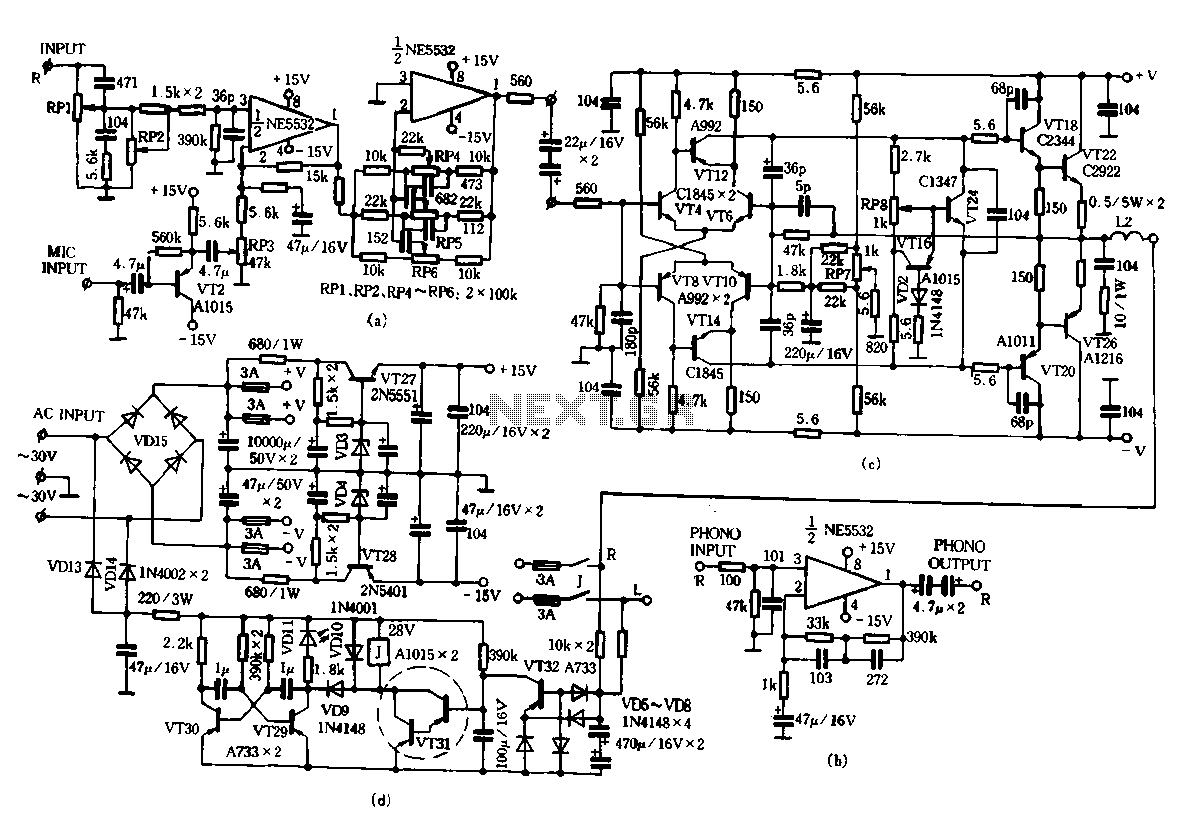
Only the R channel is shown, with the original reference PCB label. Figure (a) illustrates the front tone circuit, which consists of a common negative feedback operational amplifier in an RC circuit configuration. The microphone signal is amplified by...
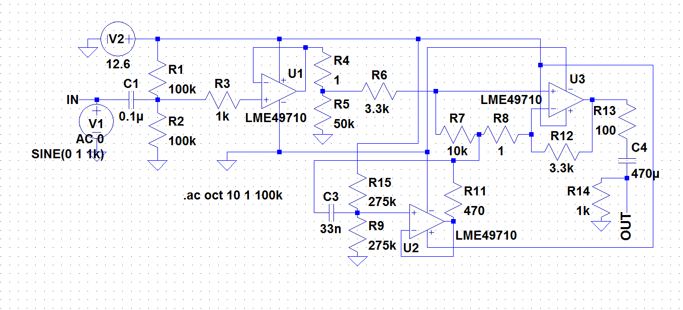
A circuit was required to function as a bass boost. The design was adapted from a circuit by ESP Sound, focusing solely on the frequency range of 35-150 Hz. The bass boost circuit, as adapted from the original design, primarily...
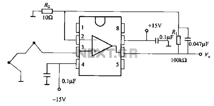
The OP07 is a low drift operational amplifier with a maximum voltage drift of 30 µV/°C and a maximum drift of 0.6 mV/V/°C. It features low noise characteristics with a maximum noise level of 0.6 pV/√Hz, offering ultra-stability with...
The major advantage of amplifiers of this type is that the normal static power dissipation is very low, and the overall power-conversion efficiency is high. Unfortunately, there are also some inherent disadvantages due to the intrinsic dissimilarity in the...