
Parametric EQ based bass boost circuit

The bass boost circuit, as adapted from the original design, primarily enhances low-frequency audio signals within the specified range of 35 Hz to 150 Hz. This frequency range is crucial for achieving a deeper and richer bass response in audio applications, making it particularly suitable for subwoofers and bass-heavy audio systems.
The circuit typically employs an operational amplifier (op-amp) configured for a non-inverting gain stage. The input signal is fed into the non-inverting terminal of the op-amp, while a feedback network determines the gain and frequency response. The frequency response is shaped by the selection of resistors and capacitors in the feedback loop, allowing for a boost in the desired frequency range while attenuating higher frequencies.
In practical implementation, the circuit may include a potentiometer to adjust the level of bass boost, providing flexibility for the user to tailor the output to their preferences. Additionally, high-pass and low-pass filters may be integrated to further refine the audio signal, ensuring that only the desired frequencies are amplified.
Power supply considerations are also essential; the circuit should be powered by a stable DC source, typically within the range of ±12V to ±15V, to ensure optimal performance of the op-amp and to minimize distortion. Proper grounding and layout design should be observed to reduce noise and interference in the audio signal.
Overall, this bass boost circuit is an effective solution for enhancing low-frequency audio output, making it an excellent choice for various audio applications.So I needed a circuit to act as a bass boost. I ended up adapting this circuit (by ESP Sound) by excluding everything but the 35-150hz part. This.. 🔗 External reference
Related Circuits
This microphone preamplifier utilizes the low-noise integrated circuit (IC) uA739. It serves as a practical example of designing an effective preamplifier for dynamic microphones. The IC contains two identical integrated preamplifier circuits, with the second preamp functioning in the...
This audio mixer circuit schematic is designed around four current-controlled amplifiers, all integrated within the SSM2024 IC. The audio mixer circuit utilizes the SSM2024 integrated circuit, which features low-noise, high-performance operational amplifiers suitable for audio applications. The SSM2024 is particularly...
It is very useful for 1 -100 watt AUDIO AMPLIFIERS This description refers to a component or circuit designed to enhance the performance of audio amplifiers in the power range of 1 to 100 watts. Such amplifiers are commonly used...
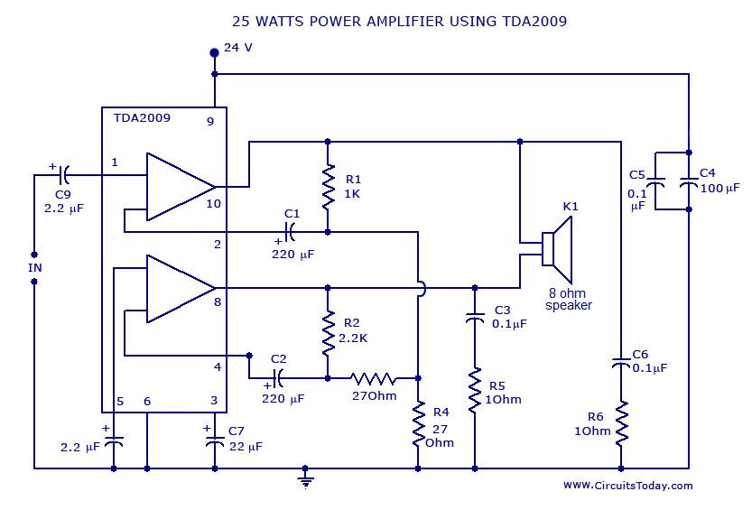
Power amplifier circuit diagram with schematics. This simple audio power amplifier circuit is designed for 25 watts output power using TDA 2009 IC, which has two channels (stereo), 12.5 W for each channel. The described power amplifier circuit utilizes the...
This is just one of the many bugging devices available on the eavesdropping market. The range includes pen and pencil holders, trophies, framed pictures, and office furniture with false bottom drawers. These products are readily sold to fledgling companies,...
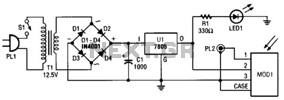
A schematic diagram for the remote analyzer is presented. The circuit is powered by a simple 5-V supply, which includes components such as PL1, SI, Tl, a bridge rectifier formed by diodes D1 through D4, capacitor CI, and a...