
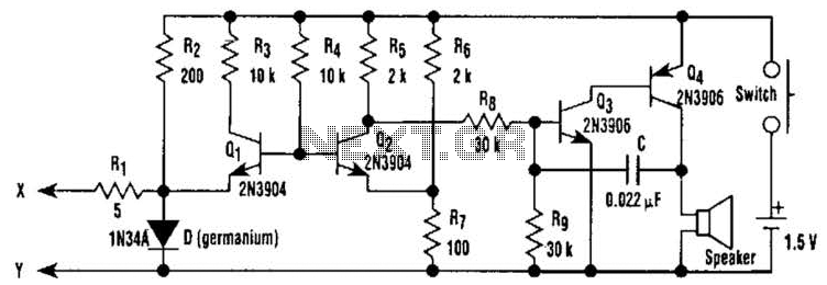
A five-way dual-channel audio switching circuit

The project involves designing a circuit that simulates the character Mu symbol, which is often represented in various applications, including animation and robotics. The core requirement is to create a bone dish SET code that can accurately manage decimal points, enhancing the precision of the output.
The circuit will utilize a microcontroller as the central processing unit, programmed to interpret the bone dish SET code. This code will dictate the position of various actuators that represent the character's features, including the mouth, which is controlled by an inverted J mechanism. The design should ensure that the inverted J structure can articulate effectively, mimicking the opening and closing motion of a mouth.
To achieve this, a motor driver circuit will be integrated to control the servos or stepper motors associated with the mouth mechanism. The left foot of the character will also be represented in the circuit, necessitating additional actuators and possibly sensors to provide feedback on position and movement.
The schematic will include power supply connections, ensuring that each component receives the appropriate voltage and current. Input pins will be designated for receiving commands from a user interface or external control system. Output pins will be connected to the motors that drive the mouth and foot movements.
In summary, the project requires a well-structured electronic schematic that encompasses a microcontroller, motor drivers, and actuators, all working in harmony to simulate the character Mu with precise movements and interactions. Can simulate the character Mu symbol, I need bone dish SET code which benefit s decimal point well Jl; inverted J to open his mouth. Left foot [ circuit diagram
Related Circuits
White noise (the sound you hear when a TV is tuned to a non-existent station) has a frequency characteristic which raises the power level by 3dB with each increasing octave, and is not suitable for response testing (and will...
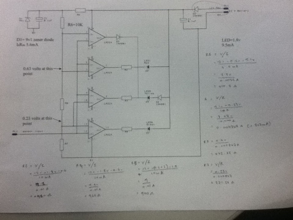
The diagram illustrates the connections for the inputs and outputs of each operational amplifier from the power source, detailing how each operational amplifier is configured to operate individual light-emitting diodes (LEDs). It also includes calculations for determining each resistor...
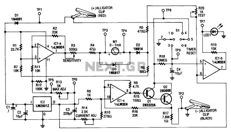
This circuit measures the cold cranking amps of a battery by discharging the surface charge and then assessing the internal resistance. This method provides a more accurate measurement than merely observing the instantaneous voltage drop under load. A constant-current...

Phase noise is a critical performance parameter of frequency synthesizers for wireless applications. RF system designers of phase-modulated cellular systems, such as PHS, GSM, and IS-54, require low noise local oscillator (L.O.) or frequency synthesizer blocks. This document describes...
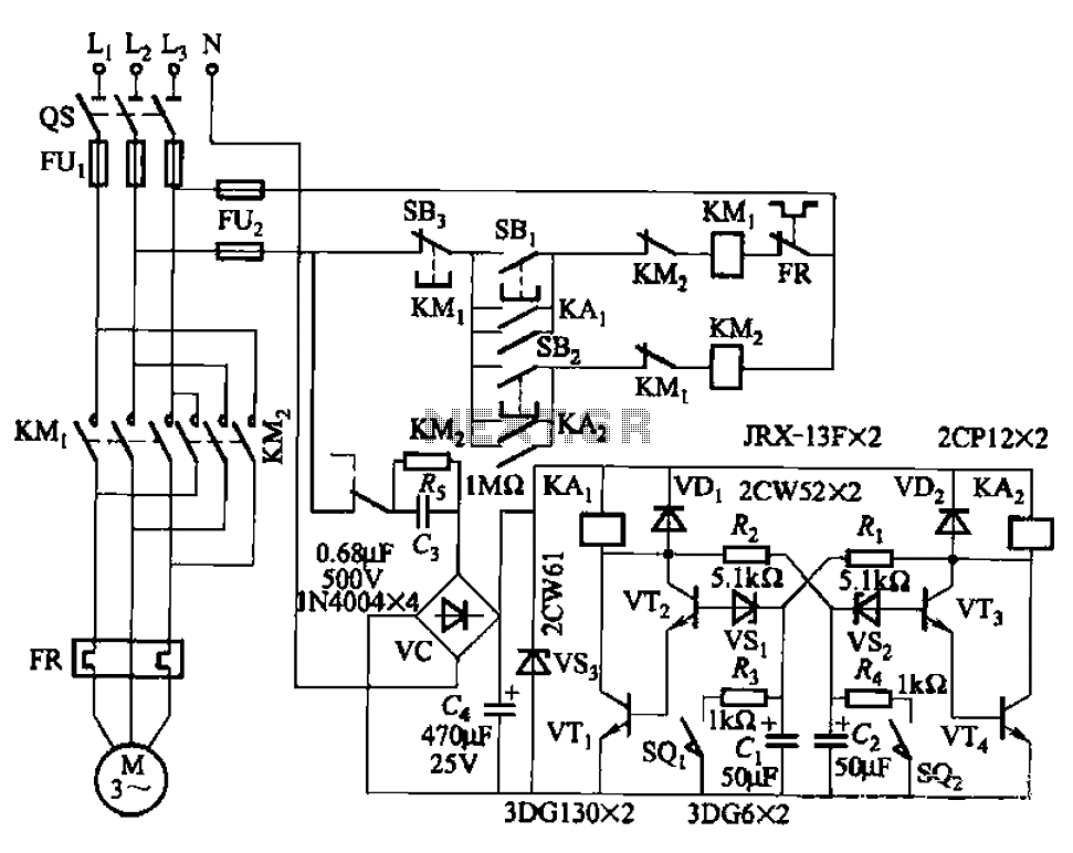
The circuit illustrated in Figure 3-72 employs a deformable bistable reversing motor control mechanism that automatically initiates and halts operation during a user-defined time delay. This feature is designed to safeguard the motor from potential impacts during the reversing...
This electronic pressure gauge utilizes a Wheatstone bridge-type pressure sensor to drive a 3 A digit A/D converter and a display. IC1 is a quad op-amp that interfaces the bridge sensor to the A/D converter. R16 allows for zero...