
A hydraulic circuit diagram showing
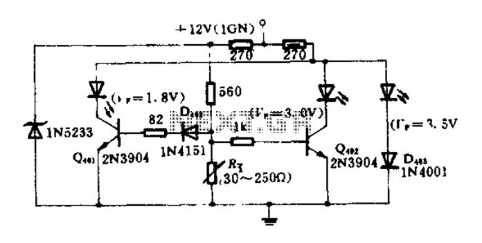
The circuit operates on the principle of using an oil pressure sensor that functions as a variable resistor, Rt. As the oil pressure in the system changes, the resistance value of Rt also changes correspondingly. This variation in resistance influences the biasing conditions of three transistors arranged in a configuration that allows them to control the current flowing to three different LEDs, each representing a specific pressure range.
The transistors are configured such that they are biased differently based on the resistance value of Rt. When the oil pressure is low, Rt increases, causing the first transistor to turn on, which in turn activates the red LED, signaling low pressure. As the pressure increases and Rt decreases, the biasing condition shifts, leading to the activation of the yellow LED at an intermediate pressure level. Finally, when the pressure reaches a certain threshold, the green LED is illuminated, indicating a safe operating pressure.
The selection of the bias resistor is critical in this design. It must be chosen to ensure that the transistors switch on and off at the correct thresholds corresponding to the desired pressure levels. This ensures that only one LED lights up at any given time, providing a clear and unambiguous indication of the hydraulic pressure status. The circuit provides a simple yet effective visual representation of pressure levels, enhancing the monitoring capabilities in hydraulic systems.FIG circuit, the oil pressure sensor is converted into a variable resistor Rt. Due to changes in Rt, changing the size of each transistor is biased, three LEDs (red, yellow, gr een) under forward bias in a different light. Therefore, as long as the bias resistor is appropriately selected, it can ensure that only one light emitting diode, to indicate the corresponding hydraulic pressure.
Related Circuits
If the transmitter stick-potentiometer delivers a voltage about 2 - 3 V, this circuit will be suitable. If you want to avoid using the battery cable (supplying Vcc for IC1 and -2), you can use a separate 5V supply...
Can someone please help explain how this circuit works? I am confident that I understand how the voltage divider network operates. The circuit in question likely includes a voltage divider configuration, which is a fundamental concept in electronics used to...
This project involves a simple touch switch circuit that can also be utilized to activate a relay instead of an LED and resistor. The circuit exhibits high sensitivity due to the use of two transistors configured as a Darlington...
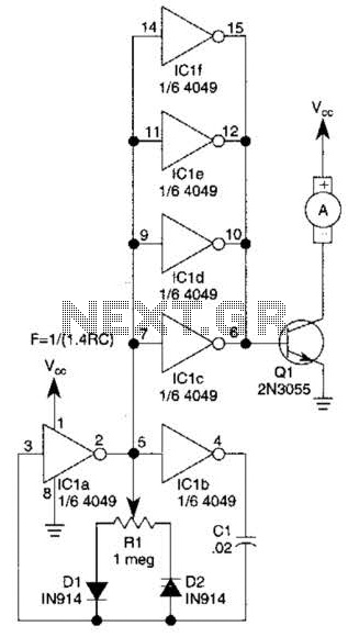
This circuit will drive a small DC motor over a wide range of speeds without stalling by controlling the duty cycle of the motor, rather than the supply voltage. The described circuit utilizes pulse width modulation (PWM) to effectively control...
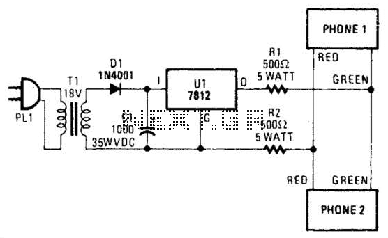
Two telephones can be used as an intercom by utilizing this circuit. Older style rotary phones that are non-electronic may be the most suitable for this application. Additionally, handsets alone can be powered in this manner. This intercom circuit allows...
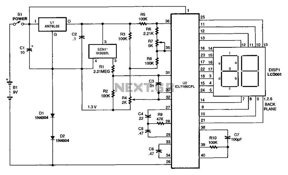
The output DC voltage of sensor SEN1 changes linearly in response to variations in relative humidity. This DC voltage is routed through resistors R1 and R2 to the analog-to-digital (A/D) converter chip U2. Resistor R4 is connected to ground,...