
Pwm Motor-Drive Circuit Circuit

The described circuit utilizes pulse width modulation (PWM) to effectively control the speed of a small DC motor. By varying the duty cycle of the PWM signal, the average voltage applied to the motor can be adjusted, allowing for precise speed control without the need to alter the supply voltage. This method is advantageous as it minimizes power loss and heat generation compared to linear voltage regulation methods.
The circuit typically consists of a microcontroller or a dedicated PWM controller that generates the PWM signal. This signal is fed into a transistor or a MOSFET, which acts as a switch to control the flow of current to the motor. The duty cycle, defined as the ratio of the on-time to the total cycle time, can be adjusted programmatically or through a variable resistor, enabling a smooth transition between different speeds.
In addition to the motor, the circuit may include protective elements such as diodes to prevent back EMF from damaging the switching components and capacitors for filtering the PWM signal to reduce electrical noise. Feedback mechanisms, such as tachometers or encoders, can also be integrated to provide real-time speed monitoring and closed-loop control, ensuring optimal performance and preventing stalling under varying load conditions.
Overall, this circuit design effectively balances efficiency and performance, making it suitable for applications requiring variable speed control of small DC motors in robotics, automation, and other electronic systems. This circuit will drive a small dc motor over a wide range of speeds without stalling by controlling the duty cycle of the motor, rather than the supply voltage.
Related Circuits

A remote-controlled alarm circuit utilizing the TSOP1736 is designed for easy use by elderly individuals or patients confined to bed. This battery-operated alarm system eliminates the need for routing electric cables to a calling bell switch, making it a...
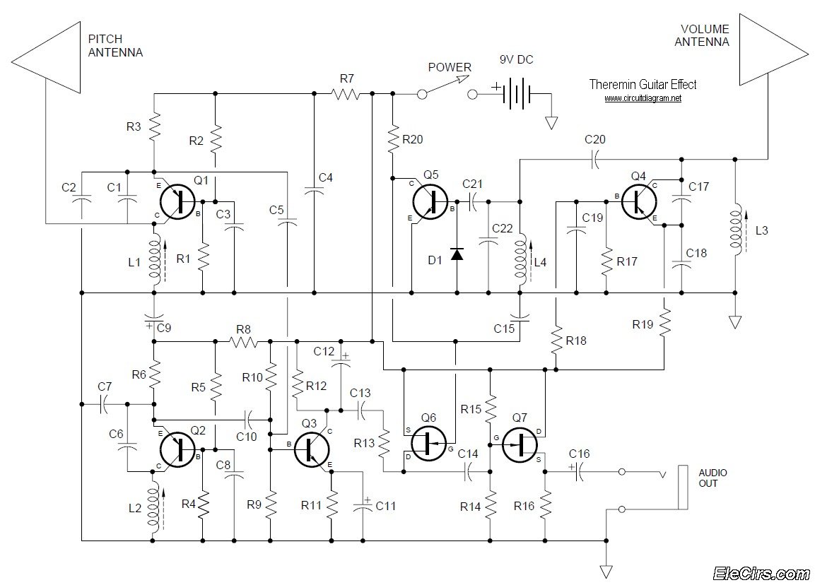
Below is the circuit diagram for the Theremin music instrument effect. A guitar or instrument amplifier is an ideal companion for the Theremin, allowing for bass or treble boost as desired, as well as fuzz (distortion) or reverberation if...
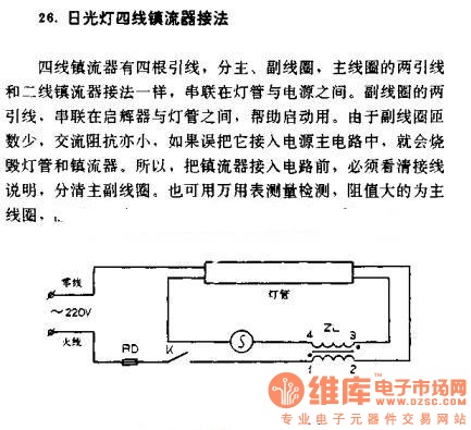
The four-wire ballast connection of a fluorescent lamp consists of four lead wires, which include main and auxiliary coils. The connection of the two lead wires in the main coil is similar to that of a second-line ballast; both...
The schematic diagram is straightforward. SW1 is a pushbutton used to start the timer. The outputs are set to logic level 0 when the timer is inactive and to logic level 1 when the timer is triggered. The relay...
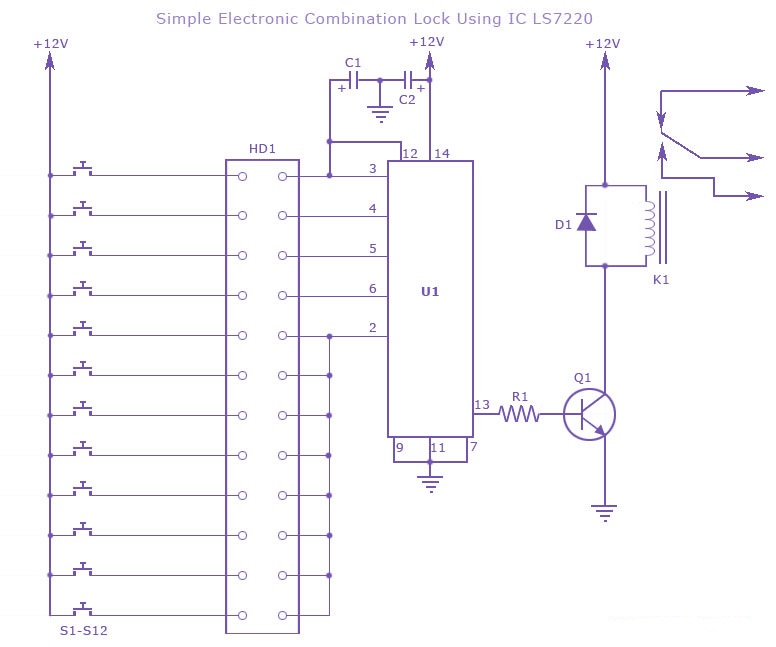
A simple electronic combination lock using the IC LS7220. This circuit employs a relay to control any device when a combination of four digits is entered. Keypads serve as the input method for entering the digits, and the correct...
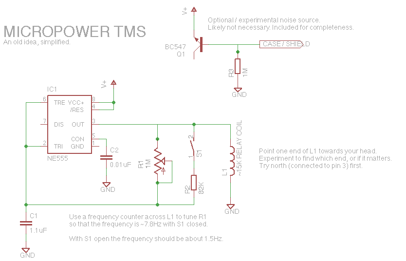
Let's face it, not every day is the greatest. Sometimes, one may not feel like doing much of anything. Wouldn't it be nice if there was a way to change brain waves at the push of a button? Transcranial...