
AM Radio Receiver Circuit With BF959 Transistor

In the context of antenna systems, impedance matching is crucial for maximizing power transfer and minimizing signal reflection. The function described indicates a circuit designed to reduce the impedance of an antenna from a high value down to a standard 50 ohms. This is particularly important in radio frequency (RF) applications where mismatched impedances can lead to inefficient transmission and reception of signals.
The circuit likely employs a transformer or an LC network to achieve this impedance transformation. A transformer can be designed with specific turns ratios to step down the impedance effectively. For instance, if the high impedance is 300 ohms, a 1:3 turns ratio transformer can be used to step down to 50 ohms. Alternatively, an LC matching network consisting of inductors and capacitors can be configured in either a series or parallel arrangement to create a matching network that achieves the desired impedance transformation.
It is noteworthy that the description mentions that this impedance transformation does not involve converting a balanced signal to an unbalanced one. This suggests that the circuit is designed to maintain the signal integrity and balance, which is essential in applications where signal purity is critical, such as in RF transmission lines or balanced antenna systems.
The component selection for such a circuit would include high-frequency inductors and capacitors that can handle the specific frequency range of operation. Additionally, careful consideration must be given to the layout of the circuit to minimize parasitic capacitance and inductance, which can adversely affect performance at RF frequencies.
In conclusion, the described function emphasizes the importance of impedance matching in antenna systems, specifically focusing on stepping down high impedance to a standard value while preserving signal characteristics. This is a fundamental aspect of RF design that ensures optimal performance in communication systems.Function: step down the antenna impedance from ‘high to to 50? and not, as would be expected, to effect a change from balanced to unbalanced. Component: .. 🔗 External reference
Related Circuits
For the simplest functions, such as a flashing indicator and/or beeper, a printed circuit board is not necessary. Components can be directly soldered onto the legs of the PIC microcontroller, using heat-shrinkable sleeves for insulation. Caution is advised to...
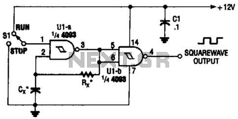
Two gates of the Quad 4093 are utilized to create an oscillator. The resistor (R) can range from approximately 5 kΩ to around 10 kΩ. The capacitor (Cx) can vary from about 10 pF to higher values, with the...
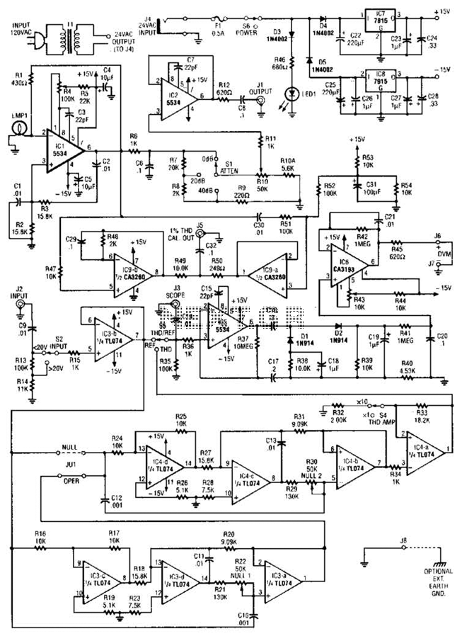
The circuit comprises a low-distortion, 1-kHz oscillator designed to measure Total Harmonic Distortion (THD) at a user-selected voltage level, suitable for voltage amplifiers or for testing amplifiers with power levels up to 600 W. It is capable of detecting...
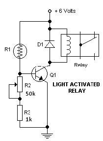
This light-dark switch activated relay circuit schematic represents one of the simplest electronic circuits designed to activate other electronic devices based on light or darkness. It requires a single electronic relay and a few common components that are not...
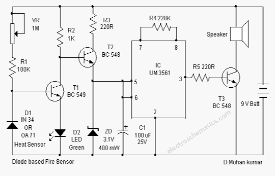
This fire sensor circuit utilizes the temperature-sensing capability of a standard signal diode, specifically the IN 34, to detect heat from a fire. Upon detecting heat, it triggers a loud alarm that mimics the sound of a fire brigade....
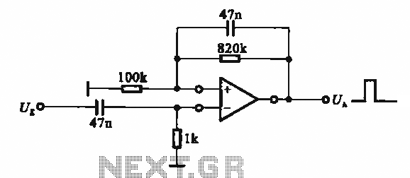
It demonstrates the use of various types of pulse signal generating circuits utilizing operational amplifiers. The circuit described involves the implementation of pulse signal generators using operational amplifiers (op-amps), which are versatile components frequently employed in analog electronics. These circuits...