
TA8210AH - 2 x 22W BTL Car Amplifier Circuit

The TA8210AH is a powerful integrated circuit designed for audio amplification, particularly in automotive and portable applications. The BTL (Bridge-Tied Load) configuration allows for higher output power while maintaining a compact design. In this circuit, two channels are utilized, each capable of delivering 22 watts to a 4-ohm speaker, making it suitable for driving speakers in various audio environments.
The circuit typically includes input and output connections, power supply filtering, and bypass capacitors to ensure stable operation. The power supply should be capable of delivering sufficient current to meet the demands of the amplifier, especially during dynamic audio peaks. It is essential to use a regulated 12-volt supply to avoid fluctuations that could affect performance.
In addition, thermal management is a crucial aspect of the design. The TA8210AH may require a heatsink to dissipate heat generated during operation, particularly at higher output levels. Proper layout and grounding techniques should be employed to minimize noise and interference, ensuring high-quality audio reproduction.
Overall, this amplifier circuit is an effective solution for those seeking a compact, efficient, and high-performance audio amplification system suitable for both automotive and stationary applications.This is a circuit of 2 x 22 watt BTL amplifier using IC TA8210AH. It is not only an auto amplifier, ideal for a low-frequency auditory approach those hi-fi, with a very good linear feature. Can be fueled by a 12 volt car battery but shi from a 12 volt charger. The chip incorporates four bridge amplifiers available in two by two in order to ensure the output 22 watts per channel on 4 ohms. 🔗 External reference
Related Circuits

An LCD (liquid crystal display) is an electronically modulated optical device composed of multiple pixels filled with liquid crystals, arranged in front of a light source (backlight) or reflector to generate images in either color or monochrome. The block...
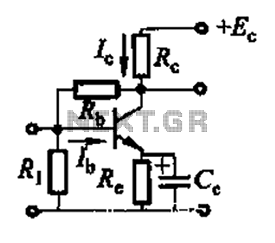
Basic reference transistor bias circuit - Mixed Negative feedback The basic reference transistor bias circuit utilizing mixed negative feedback is a fundamental electronic configuration designed to stabilize the operating point of a transistor. This circuit typically employs a combination of...
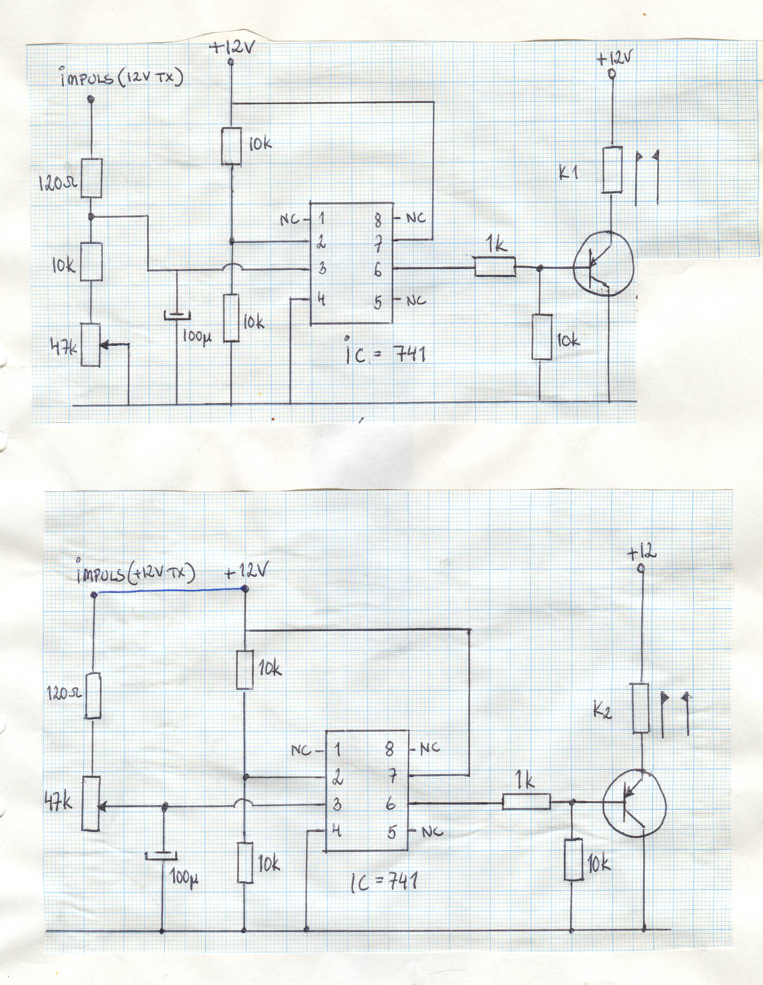
A 12-volt power supply is used to operate a sequencer board that controls external relays for coaxial relays, a preamplifier, and an amplifier. The sequencer board features DIL relays designed to drive these external relays. Although there are more...
An old ignition module from a 1978 W116 model Mercedes-Benz is being reverse-engineered. The original circuit diagram is not available, so a new one has been created based on the printed circuit board (PCB). The circuit has been assessed...
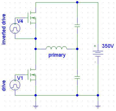
Which switch mode power supply (SMPS) topology should one start with? Although the schematic of a full-bridge looks a bit complicated compared to push-pull and half-bridge designs, sticking straight to a full-bridge topology or its smaller version, the half-bridge,...
Portable 230V lamp flasher circuit diagram. The circuit is entirely transistorized and powered by a battery. A free-running oscillator circuit is implemented using two low-power, low-noise transistors, T1 and T2. One of these transistors remains in a conducting state...